zForm Documentation
Getting Started
Here's a quick guide to installing and getting started. Please keep in mind that the user interface has had some changes and enhancements added since this video, but the basics of using many of the core features and tool are the same.
And here's a guide to using new features released on zForm 2.30.
Video Tutorials
| Title | Description | Video Link |
|---|---|---|
| Playlist of Tutorials | Here's where you can go to see all the latest tutorials released about zForm. | Watch |
| Intro to zForm | Here's a quick intro for zForm and what the tool does. | Watch |
| Installing and Getting Started with zForm | Here's a guide on installing and getting started with the tool. | Watch |
| Remove back side of mesh | To remove the back side of a mesh try following the steps here. | Watch |
| Video file | Steps to import a video file and the corresponding depth map video. | Watch |
| Directory feature | Here's a guide on using the Directory feature. Make sure the corresponding depth maps for each image match the original image file name except it will have "_depth" at the end. Also, use Blender's Timeline for each frame to go to the next image. | Watch |
Install
Follow these steps to install zForm in Blender:
- Open Blender
- Go to Edit > Preferences.
- Select the Add-ons tab.
- Click the Install... in the dropdown icon at the top right.
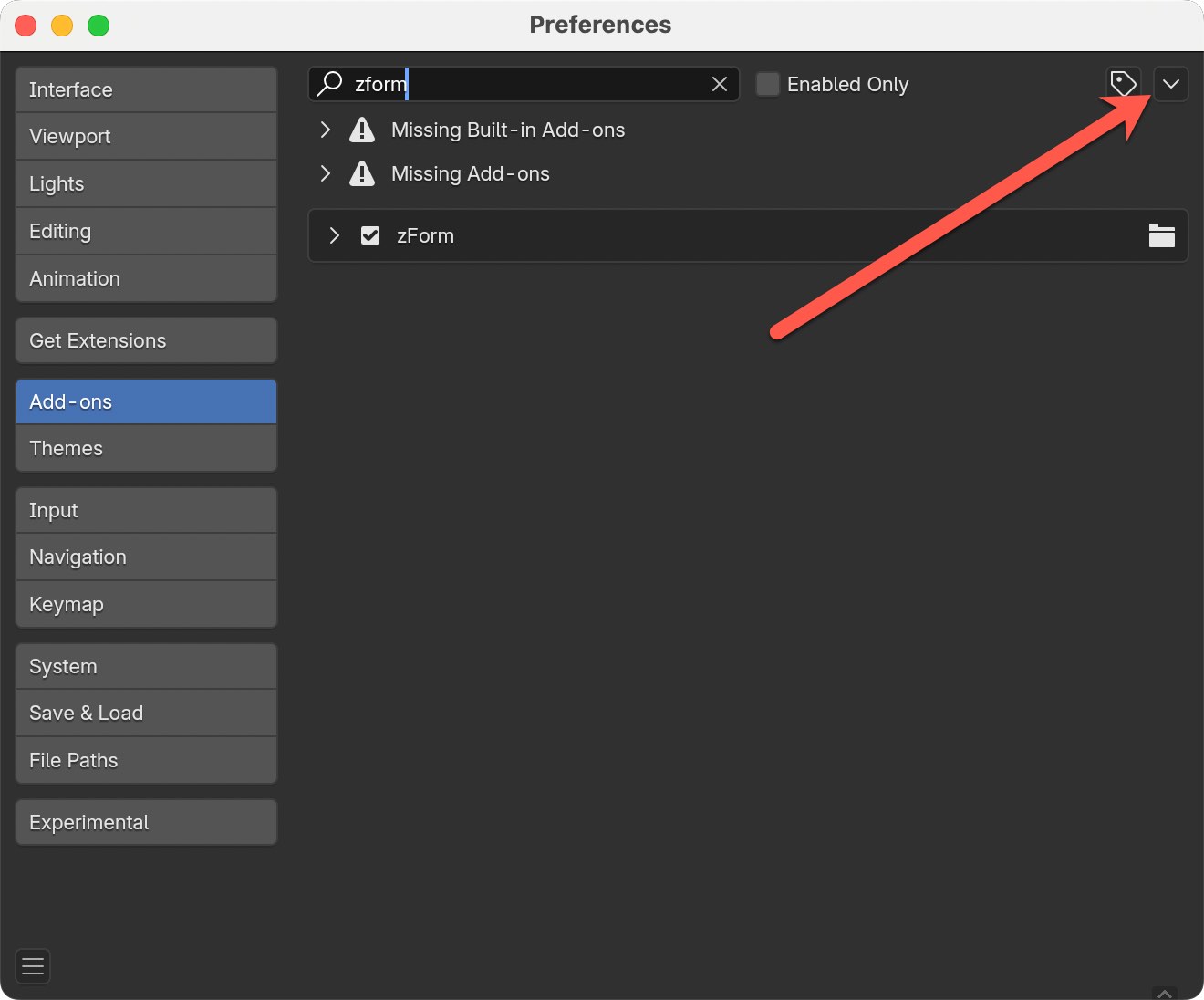
- Navigate to and select the downloaded addon ZIP file, then click Install Add-on.
- In the list of add-ons, check the box next to your addon's name to enable it.
- (Optional) Click Save Preferences to keep the addon enabled for future sessions.
Uninstall
Follow these steps to uninstall zForm:
- Open Blender 4.3.
- Go to Edit > Preferences.
- Select the Add-ons tab.
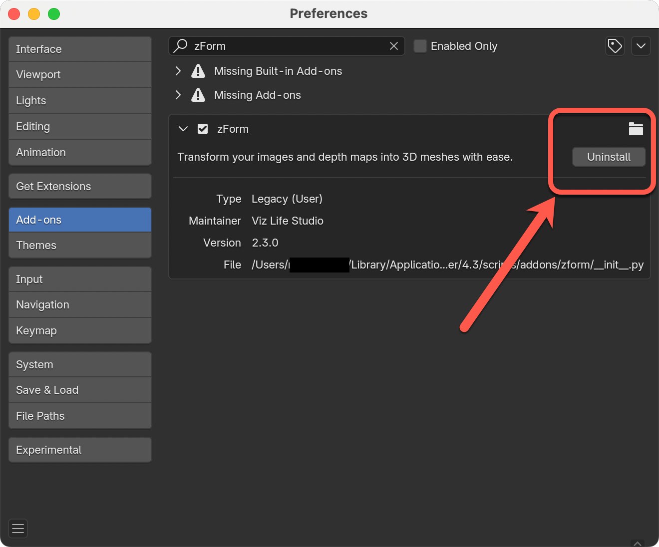
- Locate zForm in the list (you can use the search bar to search for "zForm").
- Uncheck the box next to the addon’s name to disable it.
- (Optional) Click Remove if available to uninstall the addon completely.
- Click Save Preferences to confirm the changes.
Upgrading to New Version
If you'd like to upgrade to a new version of zForm, make sure to first uninstall the old version. Then install the new version, close out Blender entirely and re-open.
User Interface
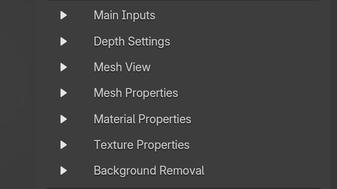
There are seven main sections in zForm including the following:
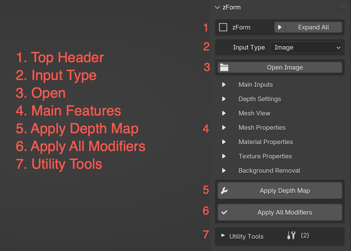
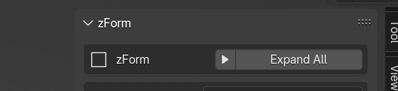
Top Header
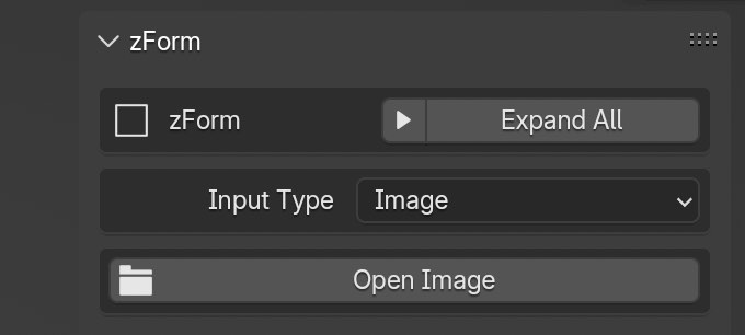
The only functionality in the top header area is the ability to expand and collapse all the main features sections. Both the little arrow icon and the button perform the same function. Click once to expand and click again to collapse.
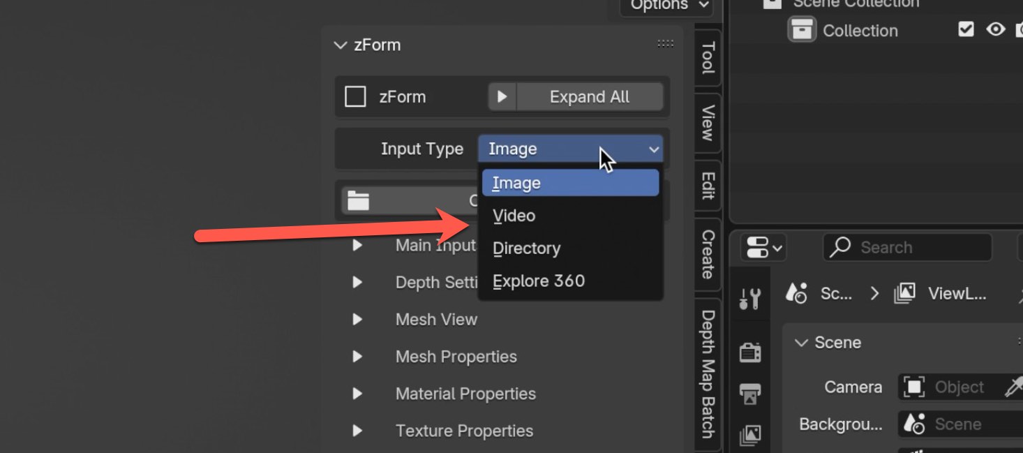
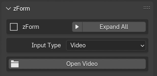
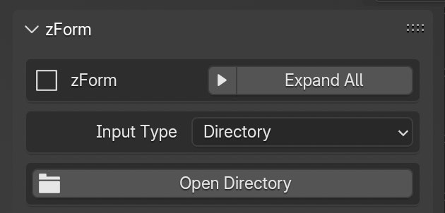
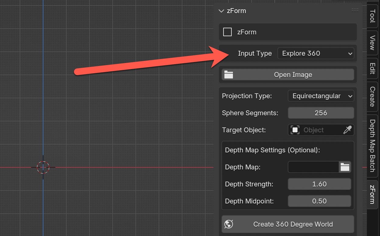
Input Type
Choose which type of input you want to use for the original source. Right now there are four options including Image, Video, Directory for a sequence of images, and Explore 360.
Image
Used to work with one single image.
Video
Works with video files, but one important thing to keep in mind is to use the Video input type, you also have to have the depth maps compiled into a video as well. If you have individual depth maps for each frame that aren't compiled into a video there are two options you can take.
Option 1: You could simply extract all the individual image frames of the video to match the individual depth map images for each frame. Then use the Directory input type. One requirement for using the Directory input type is the depth maps for each frame need to match the name of the frame, but has _ depth at the end of the file name.
Option 2: The second option is compiling your depth maps into a video file. You can do this using Blender's Video Editing tool or other tools. That being said, I found one drawback. Compiling videos for 16-bit depth maps is quite a challenge to maintain the 16-bit throughout the compiling process. Because of this I would recommend going with Option 1 for 16-bit depth maps.
Directory
If you have a directory of images and corresponding depth maps for each image, this is the option you want. This feature will take a directory of images and turn them into a sequence of images in Blender's timeline. The first frame will correspond to the first image in the directory and so on.
You can simply press the right and left arrow in the timeline to navigate to the next frame. The order of the sequence will be based on alphabetical order of the directory of images.
IMPORTANT When using the Directory input type, each depth map file name needs to match the original image name with "_depth" at the end. That's how the tool is able to match each image to the corresponding depth map.
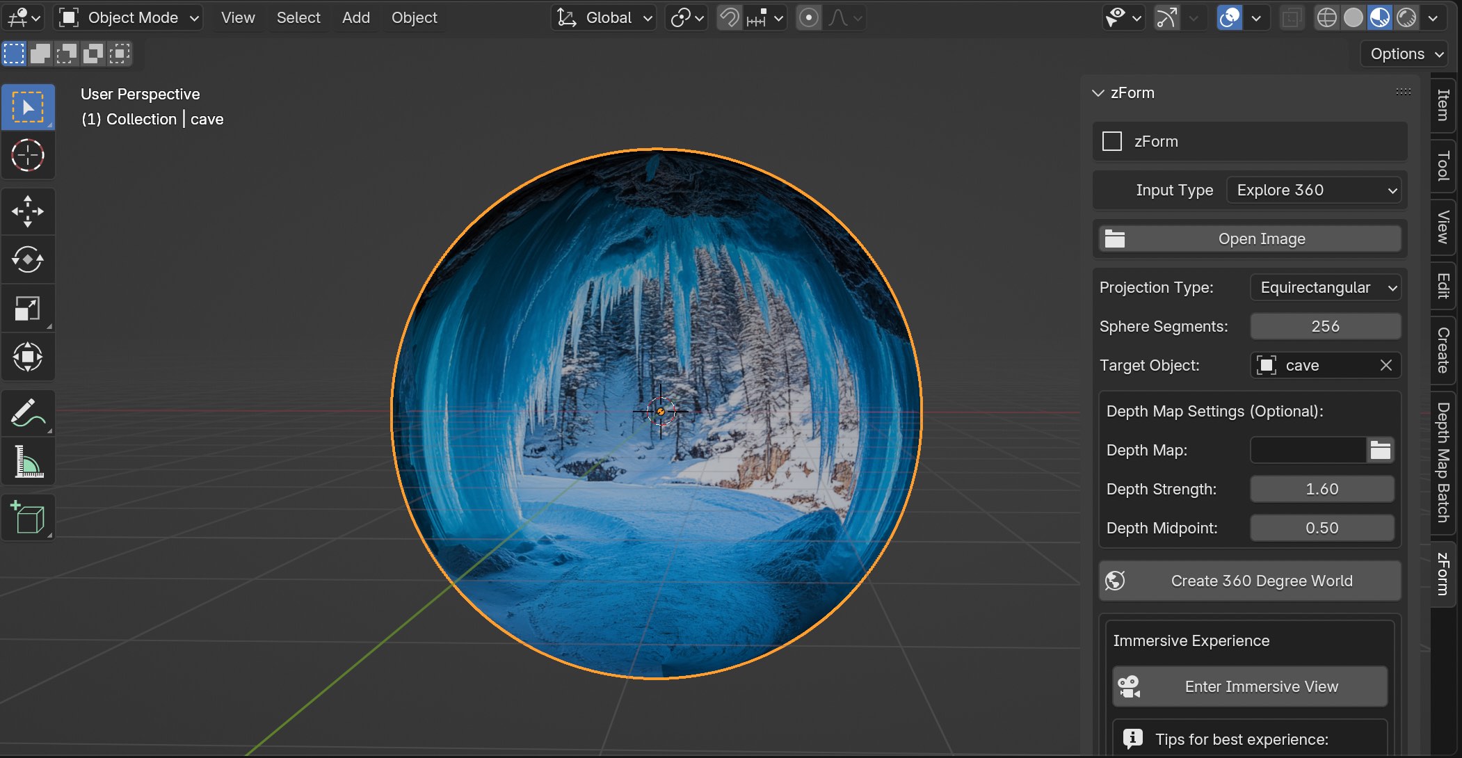
Explore 360
Take a single image and turn it into a 360 degree sphere that you can explore. Move around in 360 degrees, up, down, forward, backward. You can also record using the camera while exploring that can be turned frames for a video. Instructions on how to use this feature can be seen here.
You can create free equirectangular images using Rosebud.AI here.
Open
Depending on your input type, this is where to select your original source file(s), not the depth maps. If you chose Image as the input type, the button will say "Open Image", whereas the Video input type would say "Import Video". For the Directory input type it will say "Import Directory", but you only select the directory instead of a specific file.
Main Features
The majority of features are contained within the middle sections. I'll be covering each one in detail.
Main Inputs
Provide your depth maps here. If your input type is video, pick the compiled video of the depth maps, and if your input type is Directory choose the directory where all your depth maps are located.
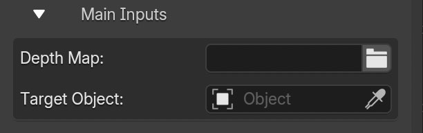
IMPORTANT You do not need to touch the Target Object, it will automatically be assigned after you specify the depth maps.
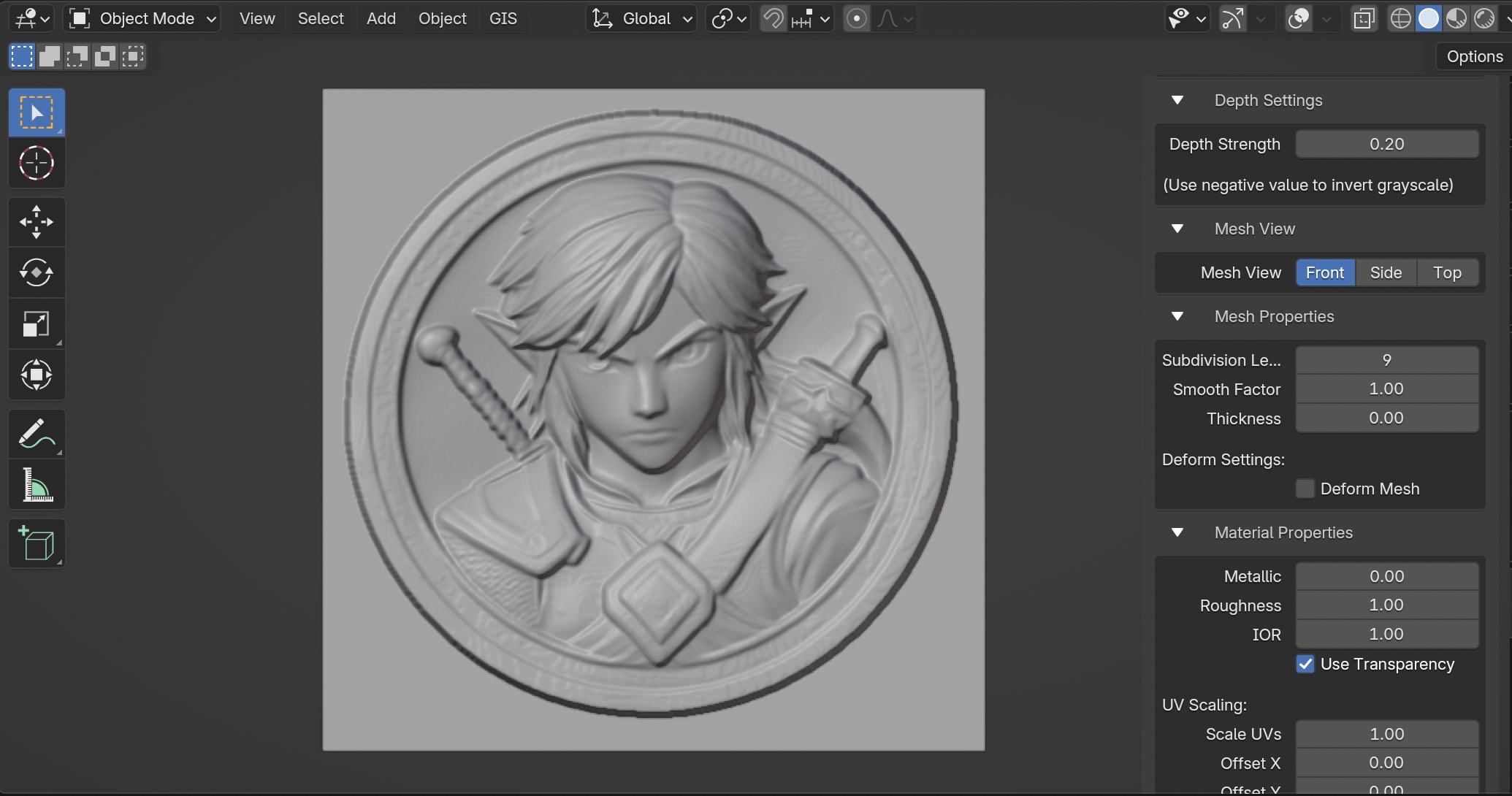
Depth Settings
Adjust your depth strength for the displacement map here. The min and max values currently are -10 to 10, but I usually stay under 1 or 2. However if you're wanting to extend depth a lot for something like a tunnel or street alleyway, then perhaps higher depth values are fitting. It's best to experiment a bit.
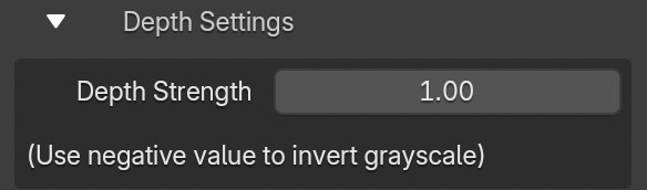
If by chance you see displacement is inverted all you need to do is flip to negative depth map values.
The reason for this could be the depth map tool you used generated depth maps where objects closest to the camera view are black, while objects furthest away are white. Typically depth maps are handled with closest objects to the camera view are white and furthest away are black.
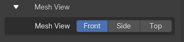
Mesh View
The add-on defaults to Top view for the mesh when using zForm, but you can change views to Front, Side, or Top. I usually work in front view with almost all use-cases with the exception of terrains, which I will use top view most of time.
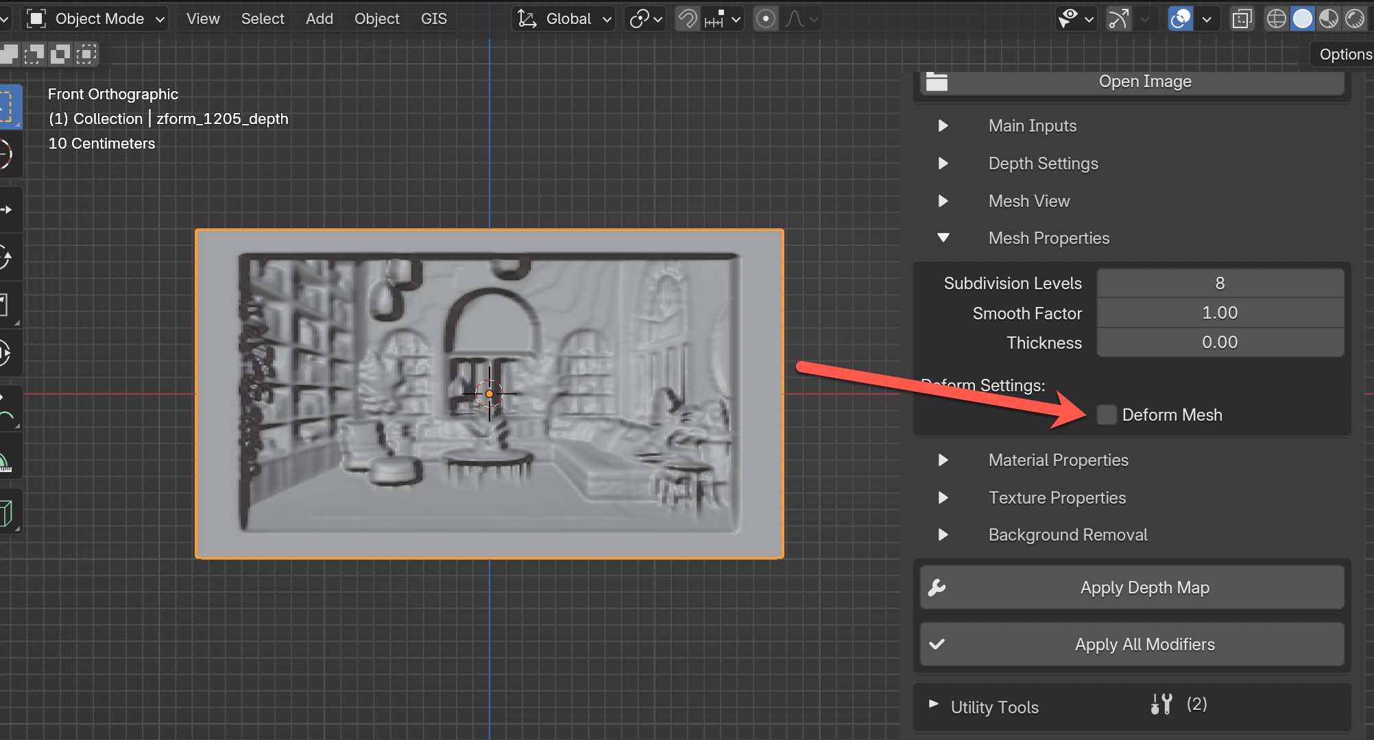
Mesh Properties
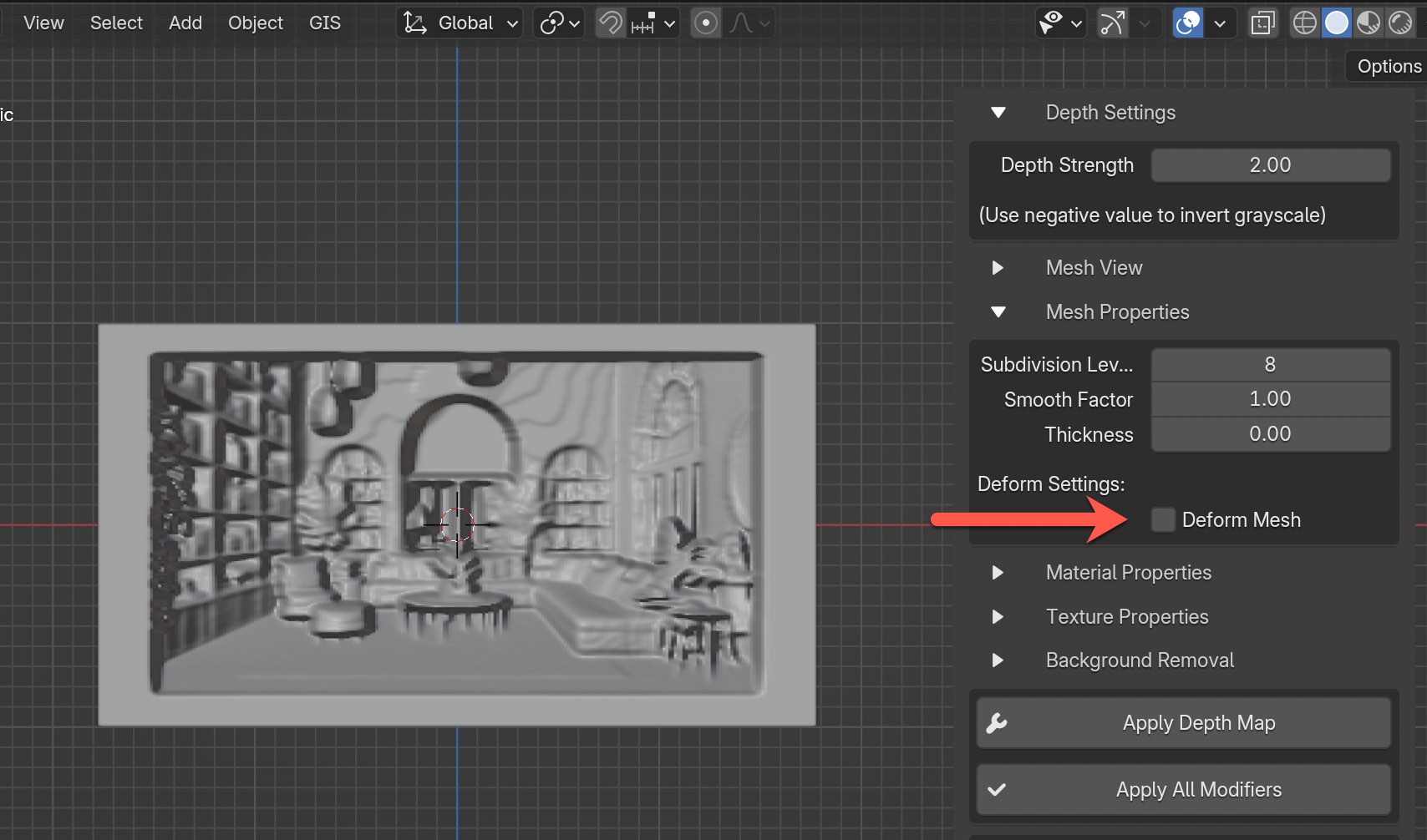
There are four features in Mesh Properties including Subdivision Levels, Smooth Factor, Thickness, and Deform Settings. Don't enable the Deform Mesh until after generating the initial 3D mesh.
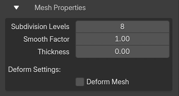
Subdivision Levels: Increasing the value will increase the density of the mesh as well as slow down performance the higher the value goes, so please keep that in mind.
I leave this value at 8 (default) while I'm adjusting other features. Only after everything is ready do I increase the Subdivision Levels above 8, though I often leave it as is. From my experience, if the depth map is in 8-bit, increasing the Depth Strength above 8 can negatively impact the mesh quality by introducing artifacts. I usually increase the Subdivision Levels above 8 only when using a 16-bit depth map.
Smooth Factor: Adjusting the Smooth Factor value will smooth the mesh by averaging angles between adjacent faces, but there is a cutoff point where increasing too much can negatively impact the mesh and create artifacts. Most of the time I will stay at 1 and no more than 2. I've been told that you can't use this feature for 3D printing, so you would most likely need to apply all modifiers before exporting the mesh.
Thickness: Rarely do I use much thickness because it can sometimes create unwanted artifacts, in fact most of the time I have it set to the default value of 0. That being said, it could still be beneficial especially for adding a little bit of thickness for 3d printing.
Deform Settings
This is a fun one! Make sure to keep the Deform Mesh feature disabled until you've generated the initial 3D mesh. Then, you can start experimenting with this one. At any time you can enable and disable the feature. If you accidentally enabled the Deform Mesh feature before generating the mesh, don't worry. Just disable and enable again.

As a starting point, once you have your 3d mesh generated check the box for "Deform Mesh" to enable this feature.
You should now see a new sphere shaped object at the origin that's displayed in wire mode. This object is assigned as the Origin object that's used to control how the mesh deforms.
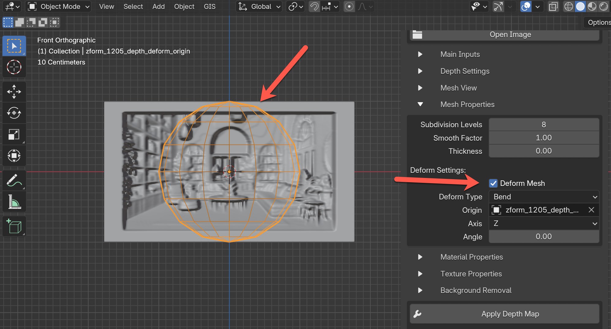
The default Deform Type value in the dropdown is Bend, there are multiple options to choose from including Twist, Bend, Taper, and Stretch.
For practice, let's use the default option for Bend and adjust the Angle to -90. Then take a look at what this does. It will bend the mesh in a clean 90 degree angle around the origin, which is the empty sphere.
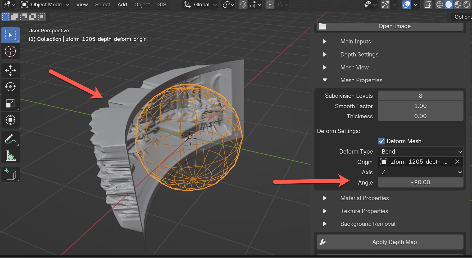
You can now see how it bends the mesh in the example above. What's import to understand is the sphere is controlling where the bend is happending. See what the bend does if you move the sphere to another location. Let's now set the sphere back to the original location.
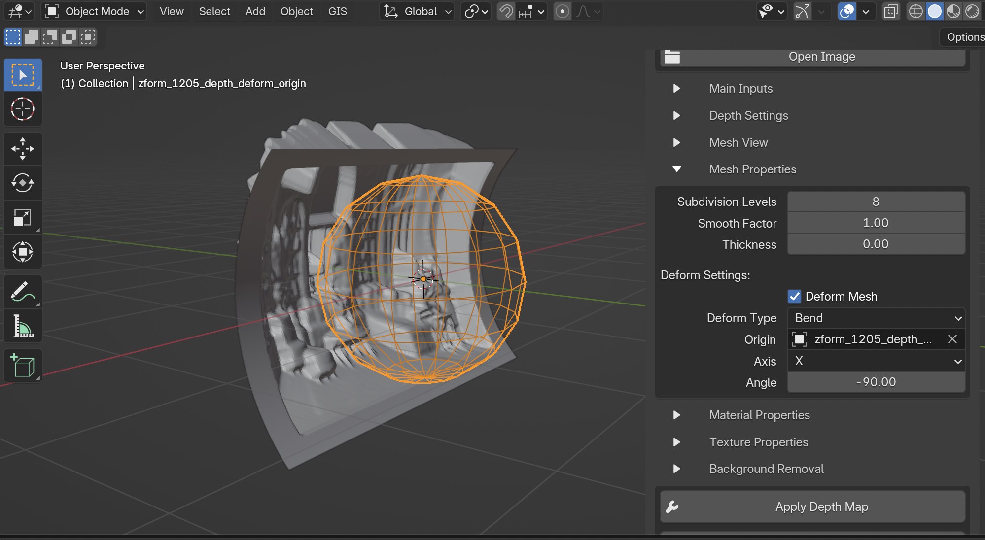
Now change the Axis to X instead of Z to see what that does.
Let's change the Axis back to Z and try something else. Change the Deform Type to Taper and move the sphere up on the Z-axis to control the slant of the floor and ceiling. And increase the Factor value up to 0.48.
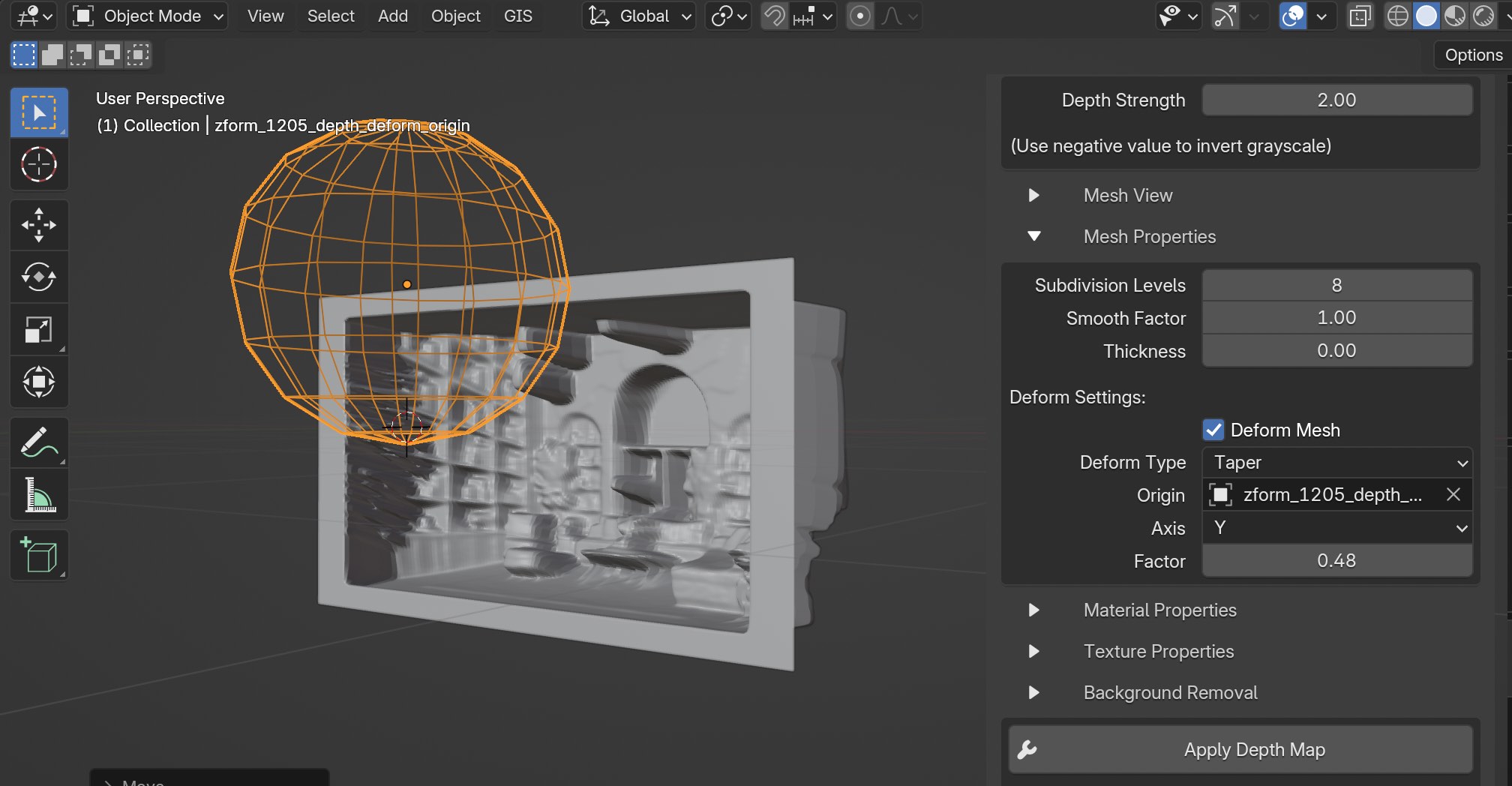
This can be useful if you need to adjust the slant of the floor area to be more flat. Now change the Axis to Z while keeping the Deform Type to Taper. You should see something like this.
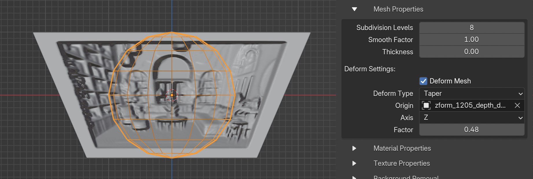
I recommend trying all the Deform Type options, moving the sphere around, and changing values for Axis and Factor. If you use Bend or Twist you adjust the value for Angle, while if you use Taper or Stretch you adjust the Factor.
There are lots of possibilities of what you can accomplish using the Deform Mesh features that I haven't expored yet. Also keep in mind that you could add key frames to the sphere to create animations.
As a last step disable the Deform Mesh feature entirely to remove all mesh adjustments using this feature, including remove the sphere object that controls the deform. You should now see the feature removed entirely.
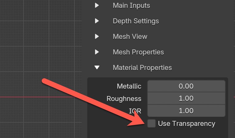
Material Properties
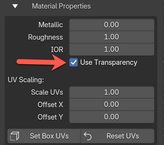
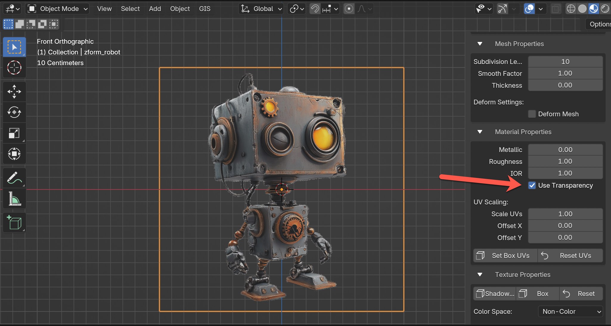
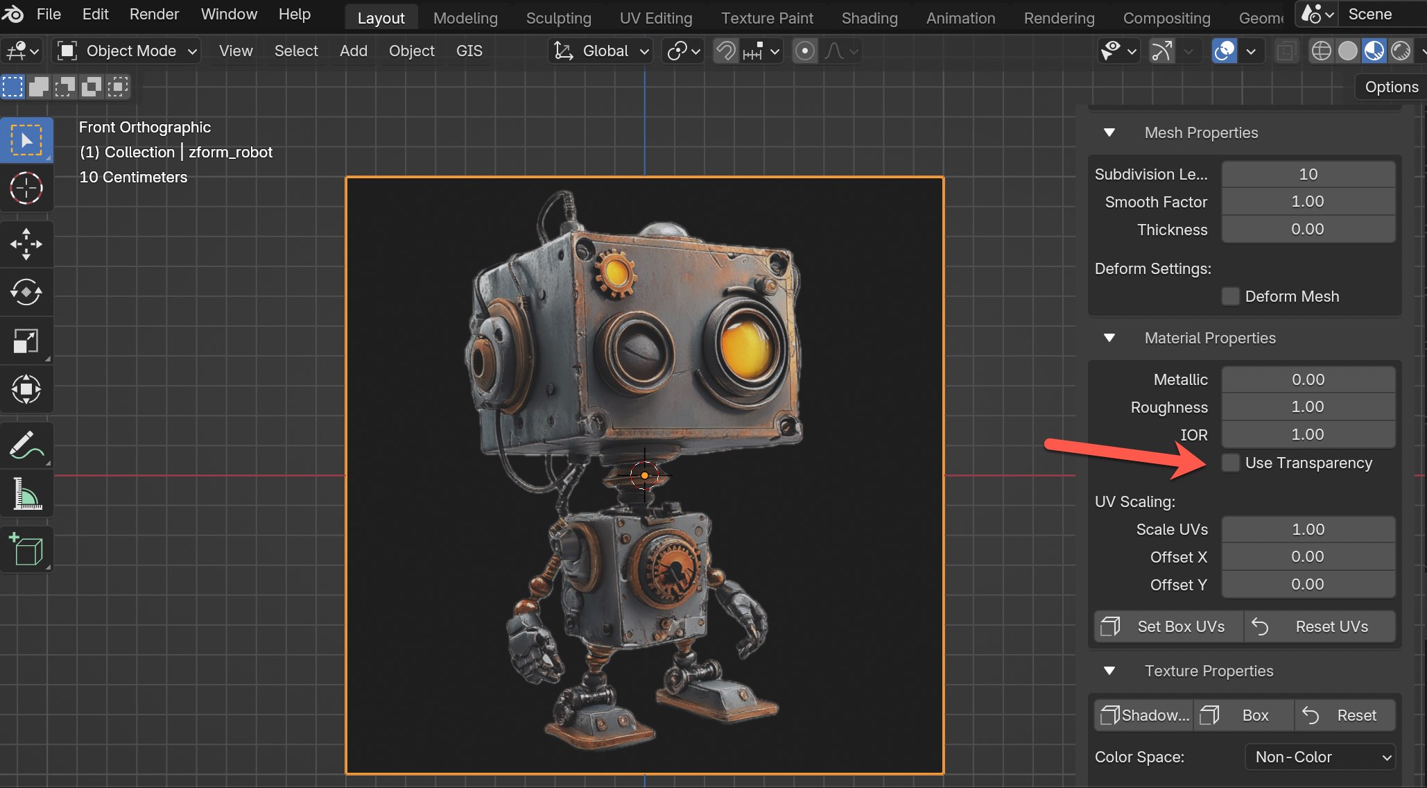
With the exception of the "Use Transparency" feature, I rarely adjust anything else in the Material Properties section. If you have transparency in your original image that you'd like to be reflected in Material Preview or Render Preview mode, you would enable the Use Transparency by checking the box, and vice-versa if you want transparency off.
Use Transparency
IMPORTANT: For those using zForm to export meshes with materials, please ensure you disable the "Use Transparency" option in the Material Properties section before export. This step simplifies the material and helps preserve the original image colors.
Here's what it would look like with "Use Transparency" enabled.
And here's what it looks like with transparency disabled.
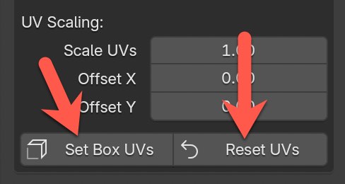
You have the ability to adjust scaling of UVs as well as offset both the X and Y axis. At any time you can click on the "Reset UVs" to reset back to default.
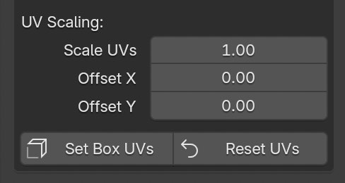
And the "Set Box UVs" button can be used to adjust UVs if you created a Shadow Box or Box using features in the Text Properties section.
Texture Properties
Quite an extensive set of features in this section. All of the adjustments made here will be based on the depth map, not the original image. In summary, these features give you more control on changing the geometry of the mesh and displacement map.
As a starting point to help explain things better, here's an example of a robot mesh.
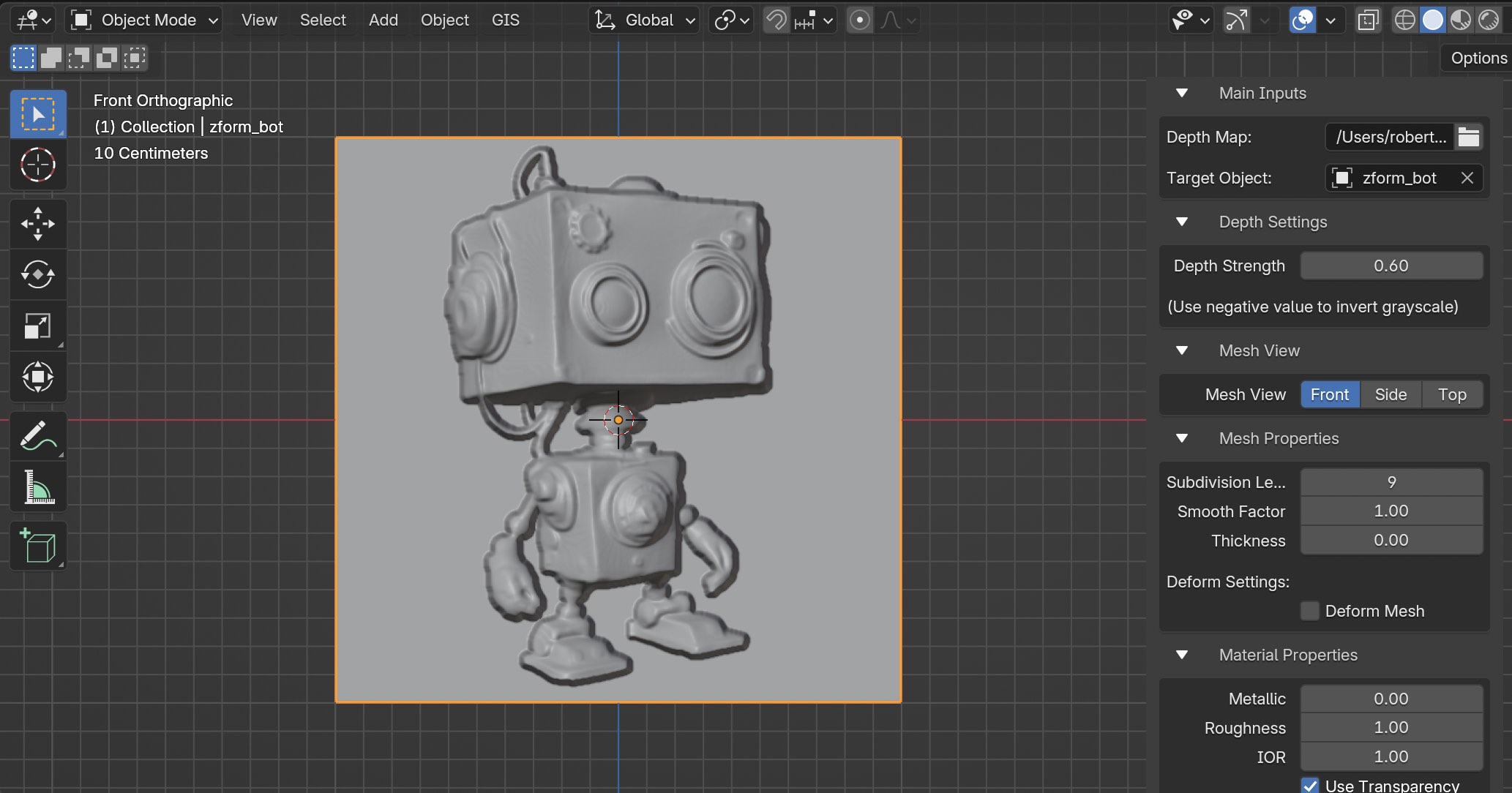
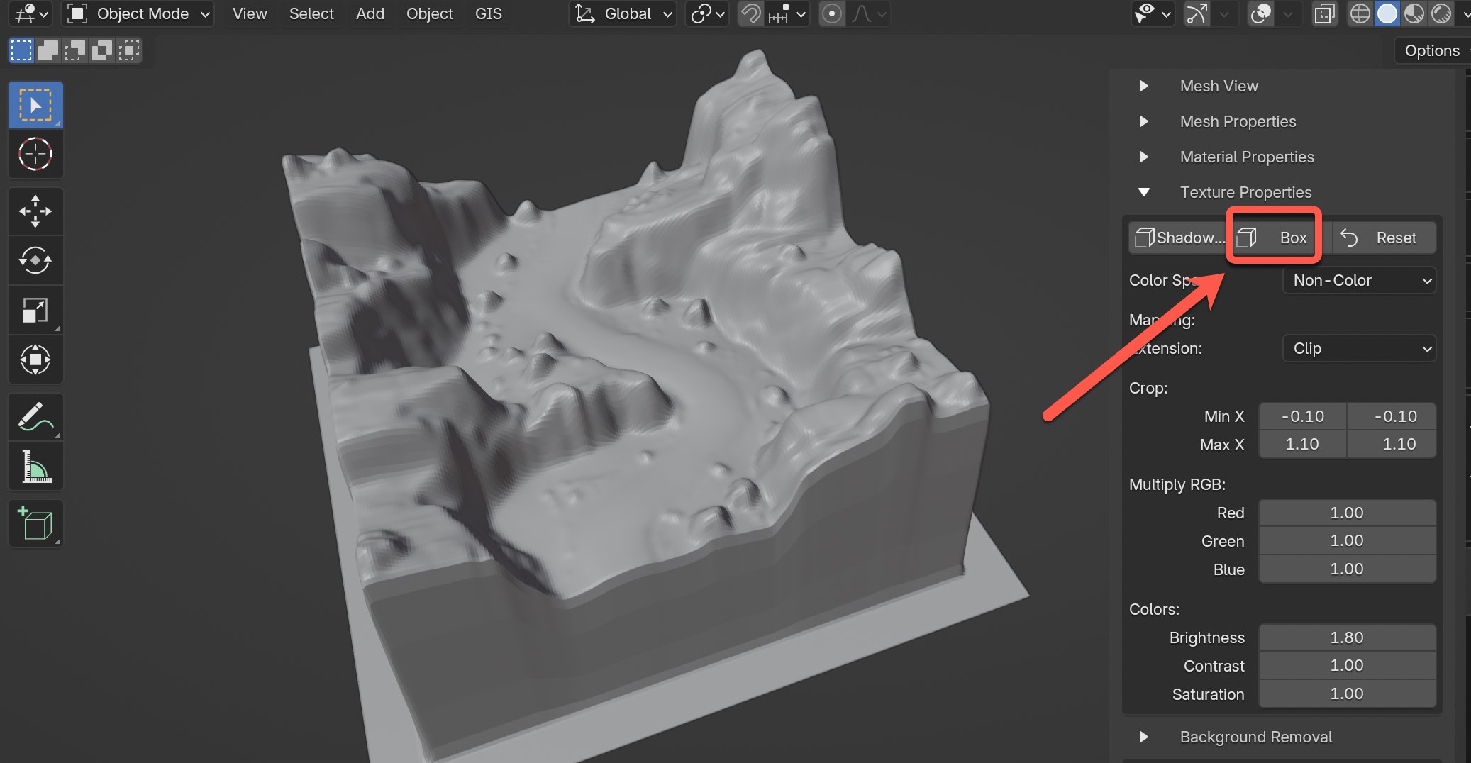
Scroll down to the Texture Properties section. We're first going to covert the three options in the very top icons. The first two options are presets where the mesh will be changed to create a shadowbox and a simple box.
Shadowbox and Box
Click on the first option for "Shadowbox".
You should now see results that look like a shadow box shown in the example below. It leverages the Texture Properties features, but minimizes the steps involved.
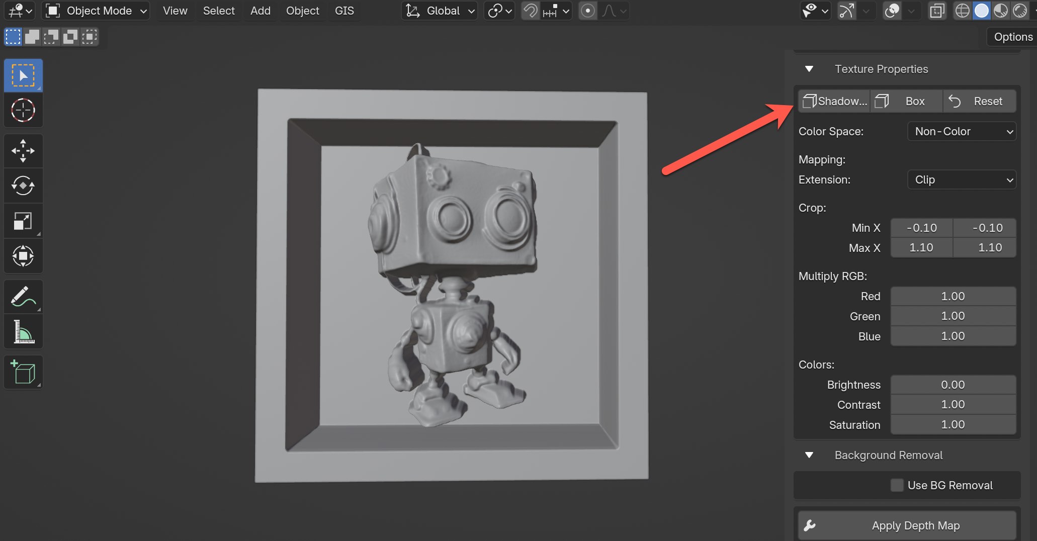
Now, in the top right in Texture Properties click on the "Reset" button, which will reset all texture property values to the default.
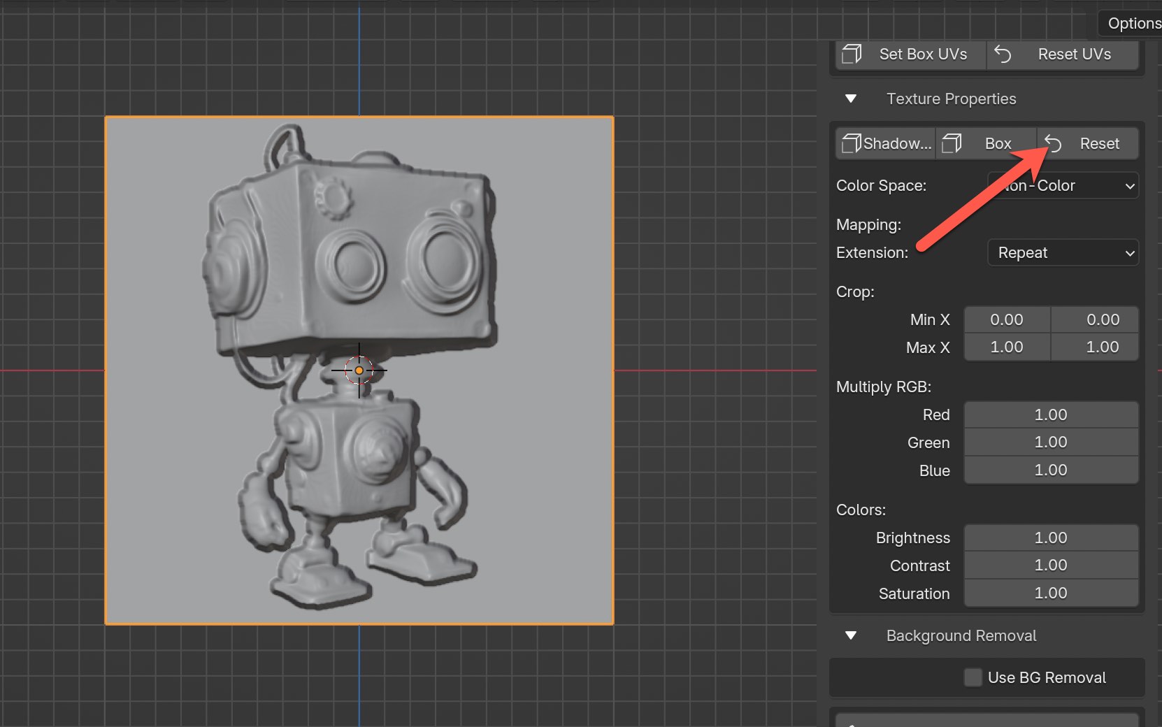
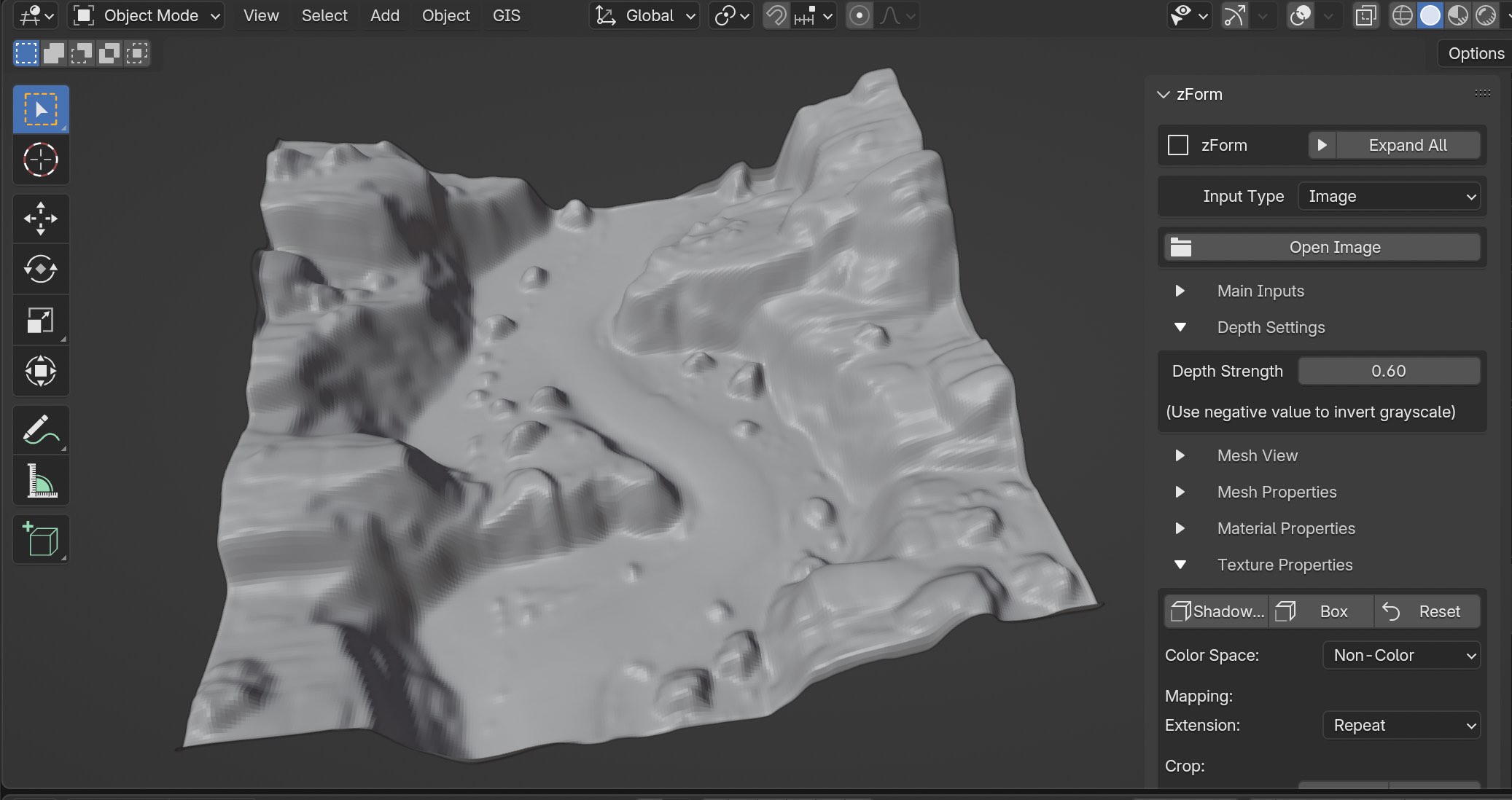
Next, let's try the "Box" preset. For this exercise I'm going to use a different mesh for a terrain that's shown below. I'm also going to change the Mesh View to Top so the ground is facing correctly and set the Depth Strength to 0.6.
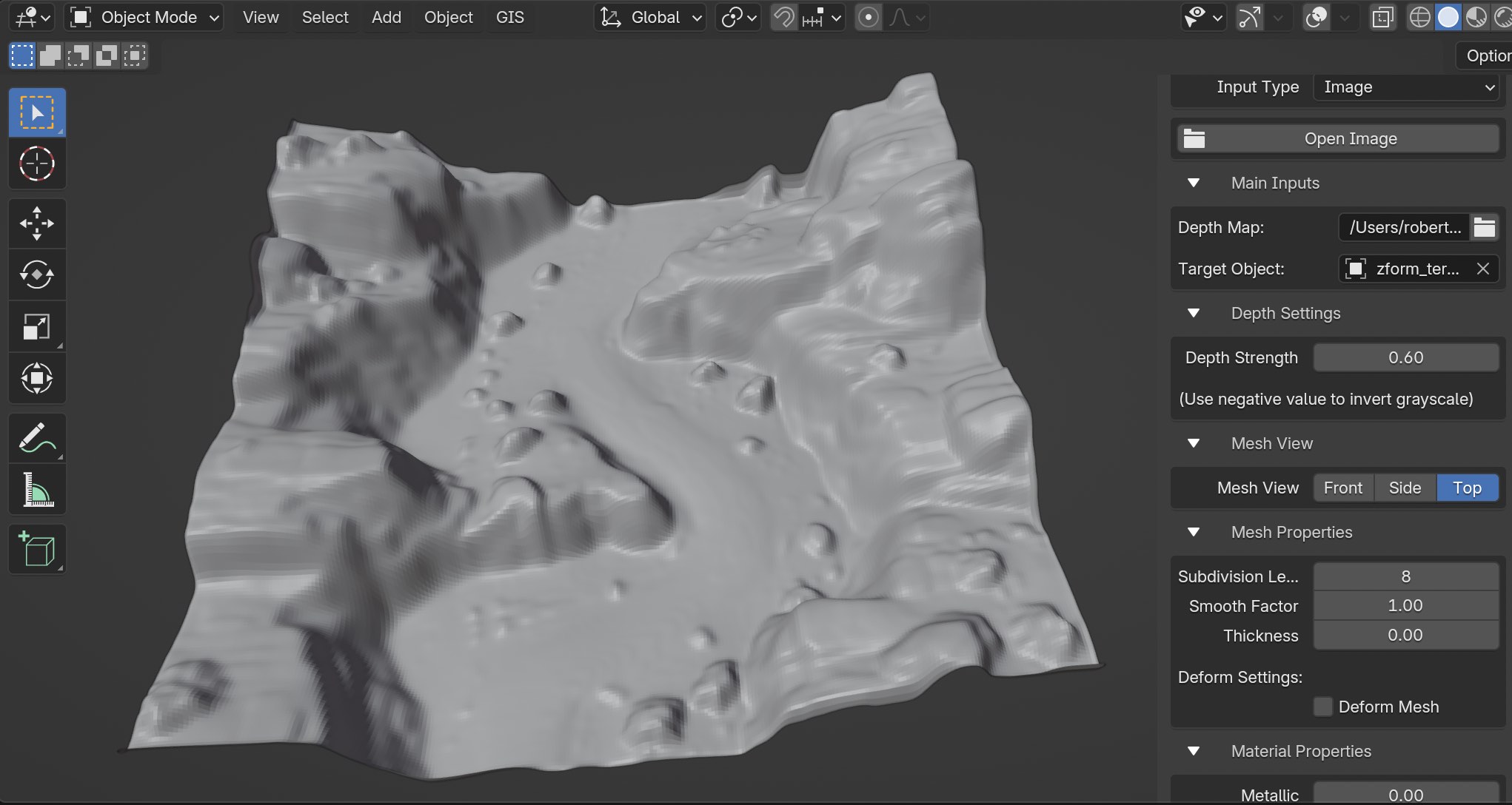
At the top of Texture Properties click on the "Box" icon and take a look at the results.
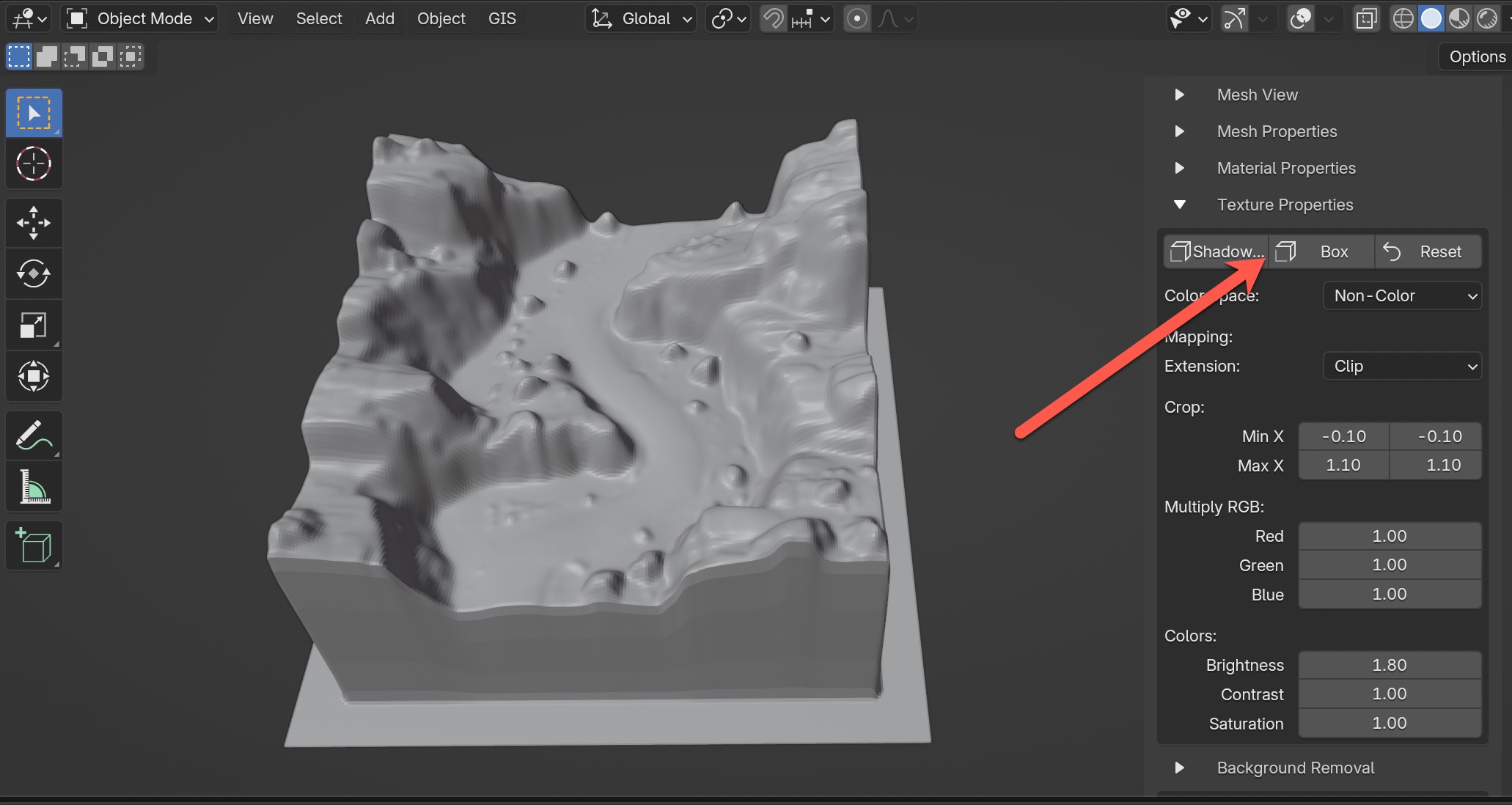
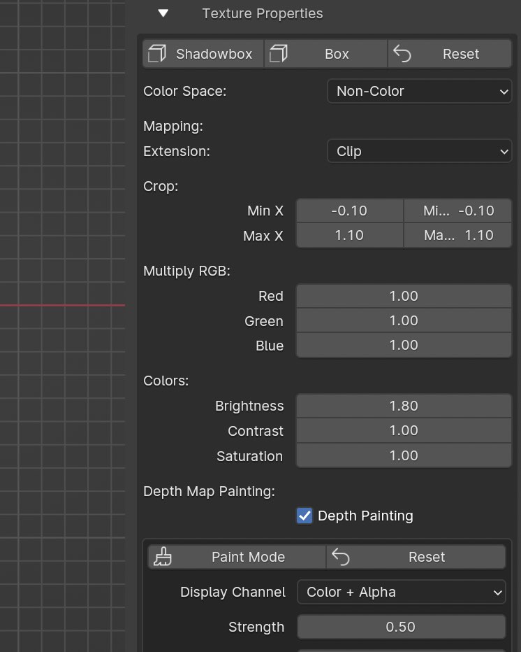
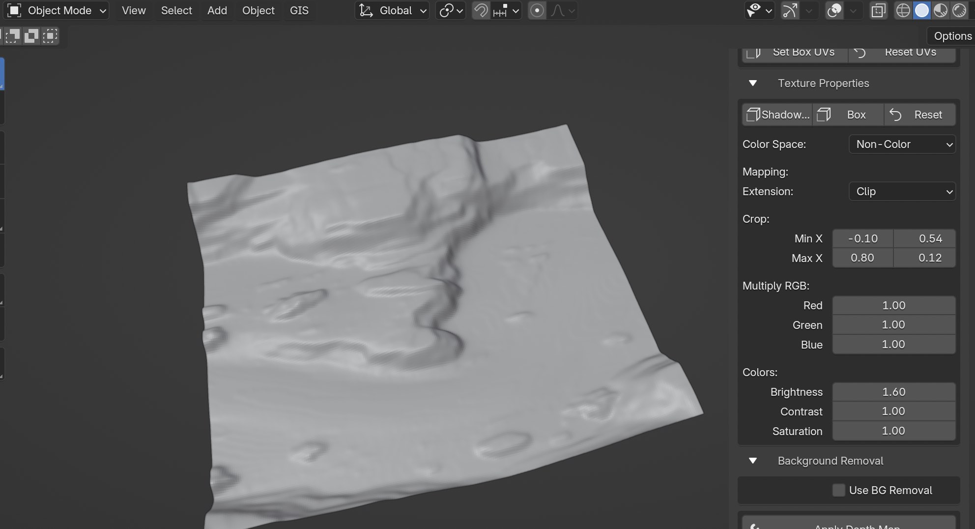
You can adjust pretty much anything you want after clicking on the preset. It just helps get you started. Take a look at the values used in Texture properties including the Mapping Extension for Clipping, Crop, and Brightness.
Contrast, Brightness, and Saturation
Now increase the Contrast value up to 2.0, which will increase the contrasts between the brightest and darkest colors.
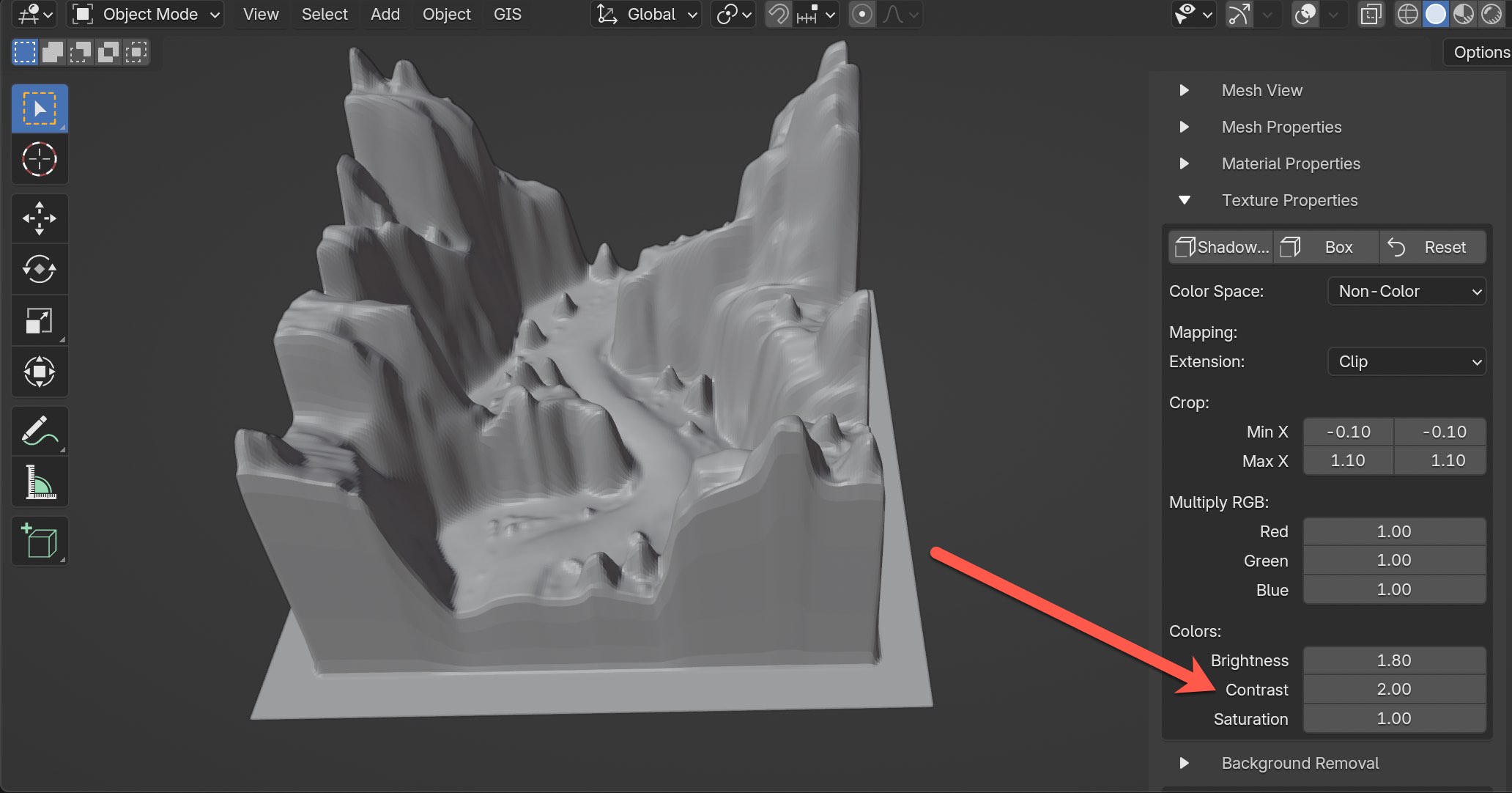
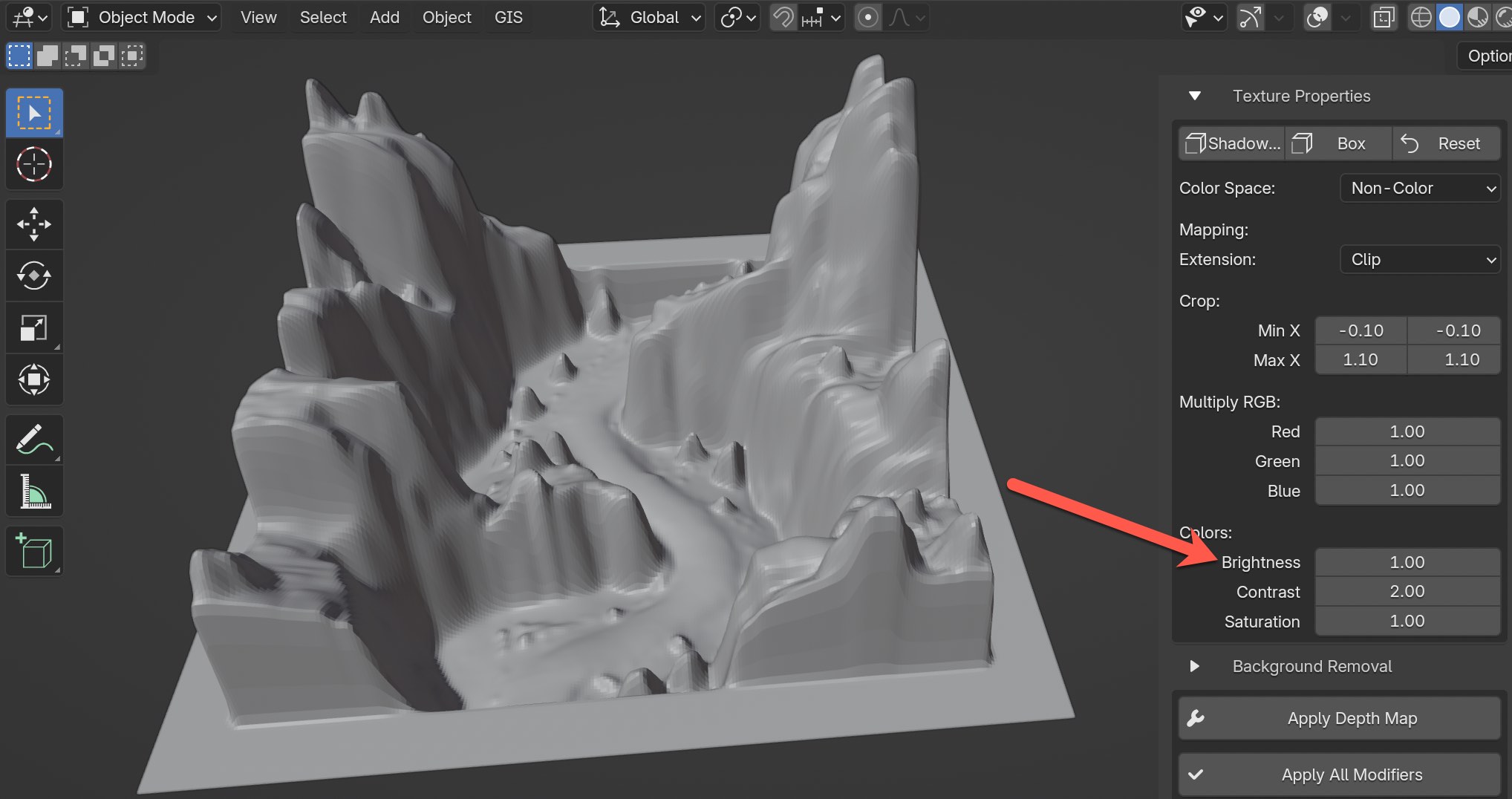
Let's drop the Brightness value down to 1.0 to see what happens. Do you see how it changed the height of the terrain?
It's a good time to point out that if you have a color depth map instead of a pure grayscale, try changing the Color Space from Non-Color to sRGB and experiment with adjust the Red, Green, and Blue values in the Multiply RGB section.
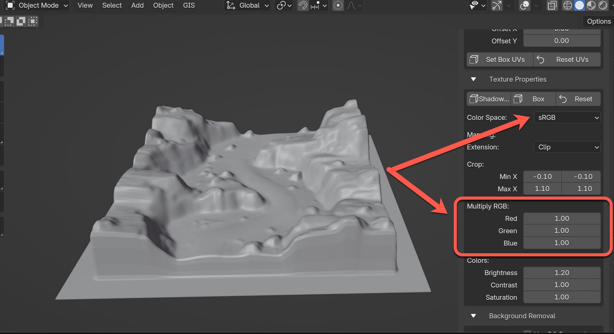
I'm going to increase the Brightness value back to 1.6 and switch back to Non-Color for Color Space.
Also try experimenting with adjusting the Crop values for the Min X and Max X. This altered how my terrain mesh looked shown below, but keep in mind the perfect box will most likely be messed up now. You can always just click on any of the presets again or reset texture property values.
Let's now click on the "Reset" button in Texture Properties to go back to default values.
Color Space
Adjusting Color Space value can sometimes produce differences in the mesh, while other times not so much. So far it's been a hit or miss for me. I've found more success with changing Color Space options using 16-bit depth maps, but I'm not sure the answer why yet. And to be honest there are times I see no difference at all between options.
For example, let's take a look at the differences when using Non-Color and sRGB for this terrain.
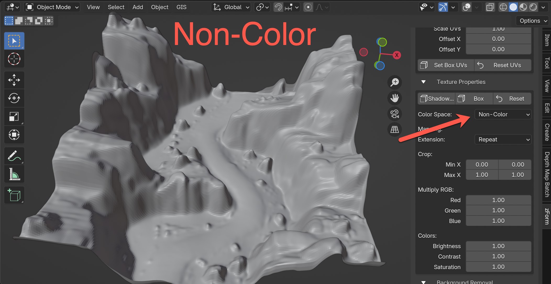
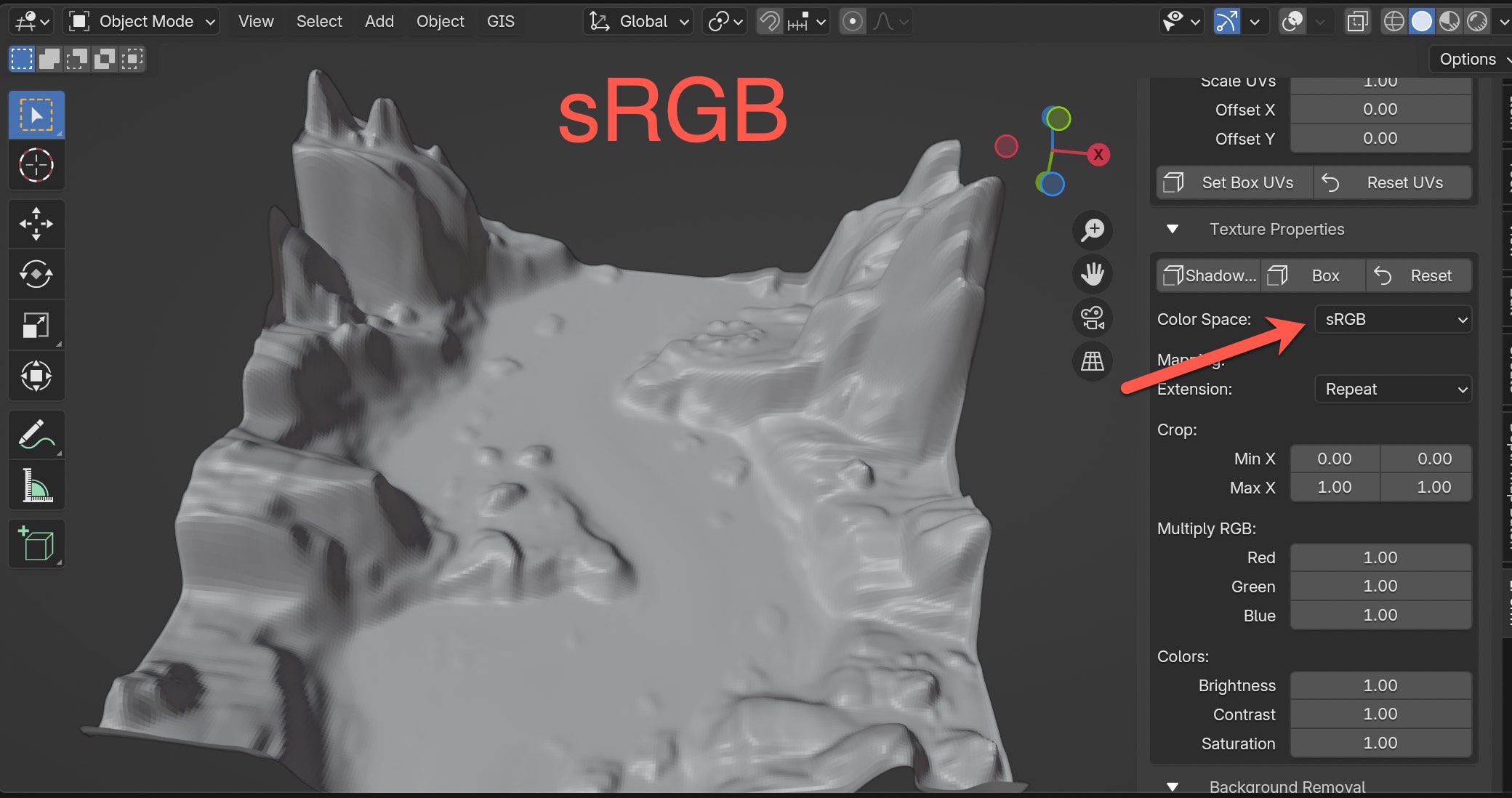
Quite a big difference in results for the rocky ground area. Personally I like using Non-Color more, however it probably depends on the circumstance.
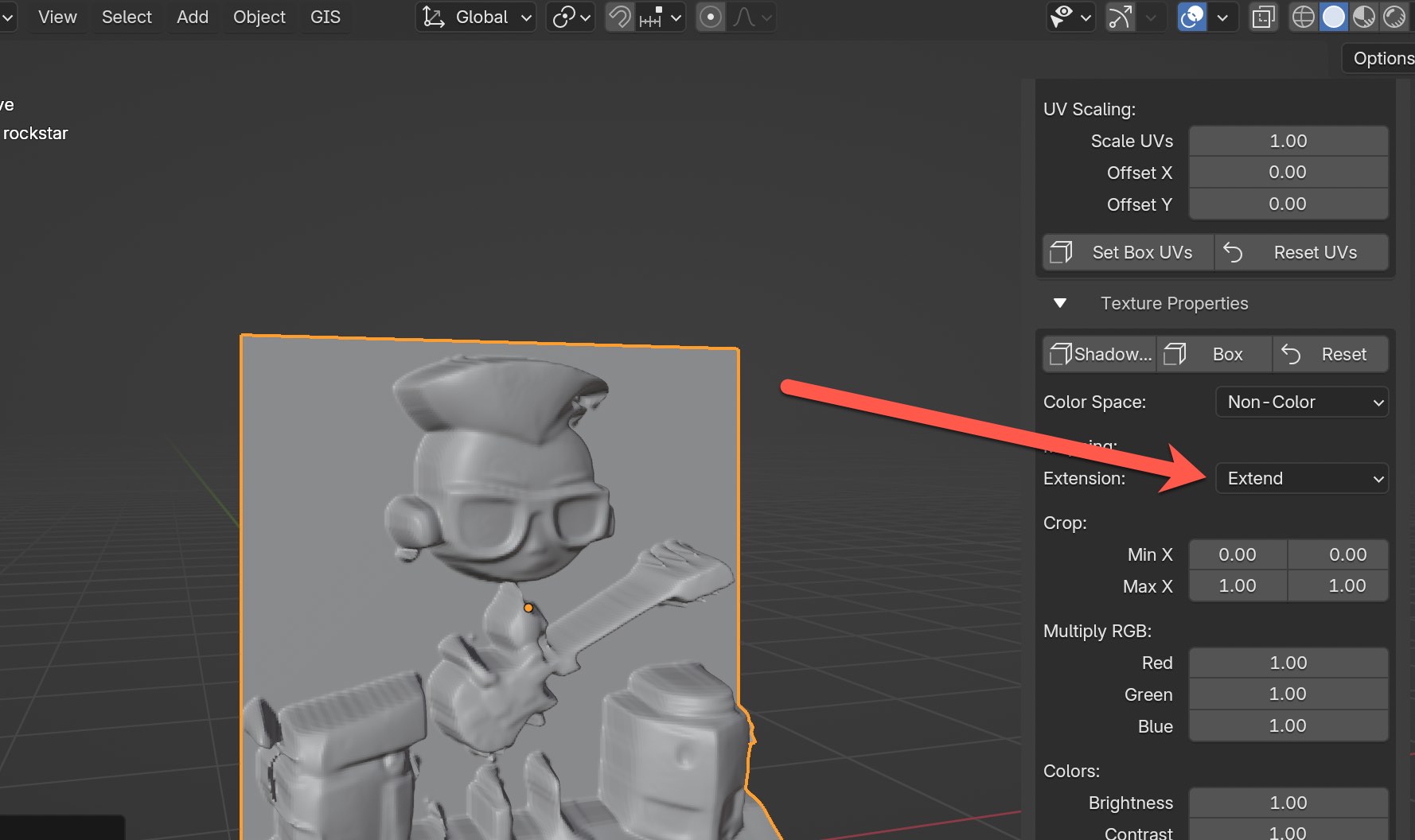
Mapping Extension
There are three options for mapping extension including Repeat, Extend, and Clip and the current default for Mapping Extension is Repeat. Each option has it's own use cases.
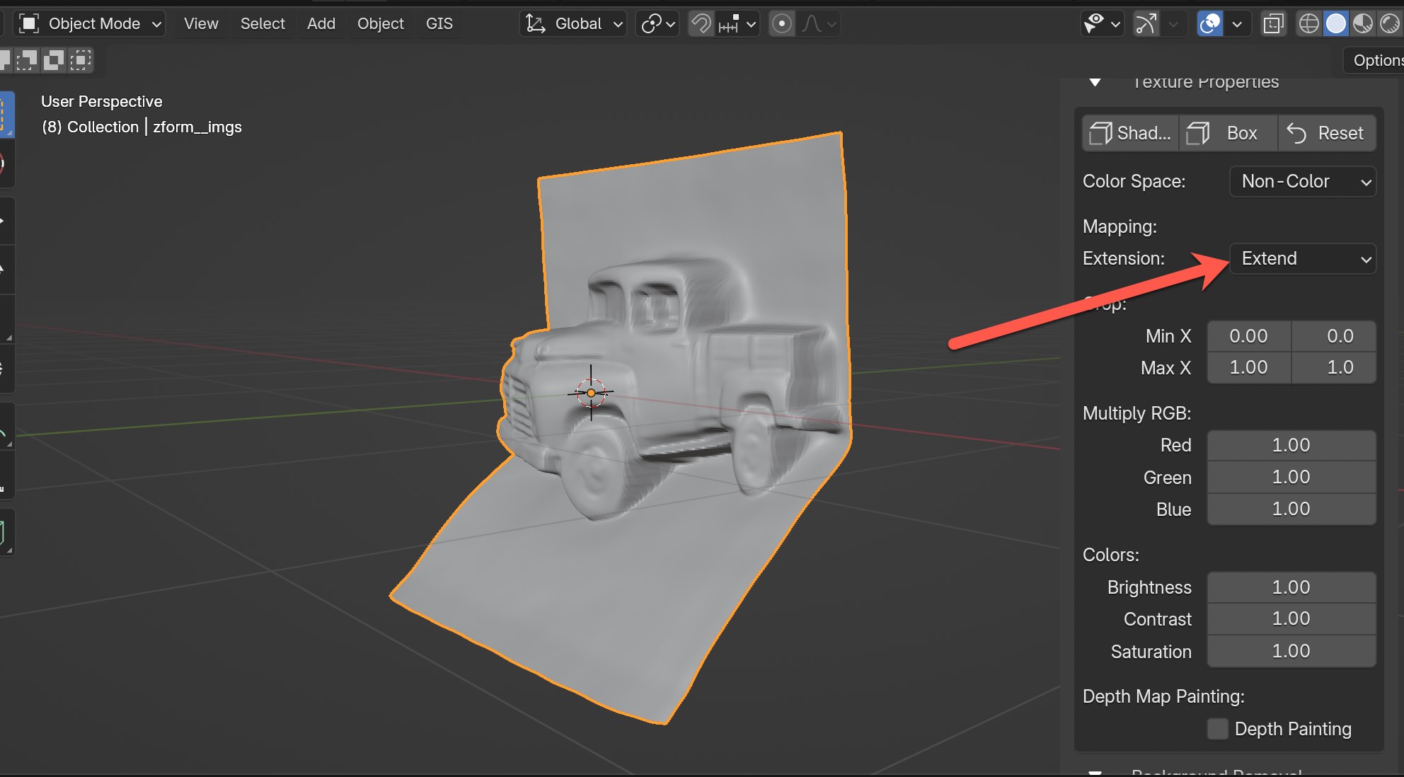
For example, there are times when your mesh might have this little unwanted fold at the top.
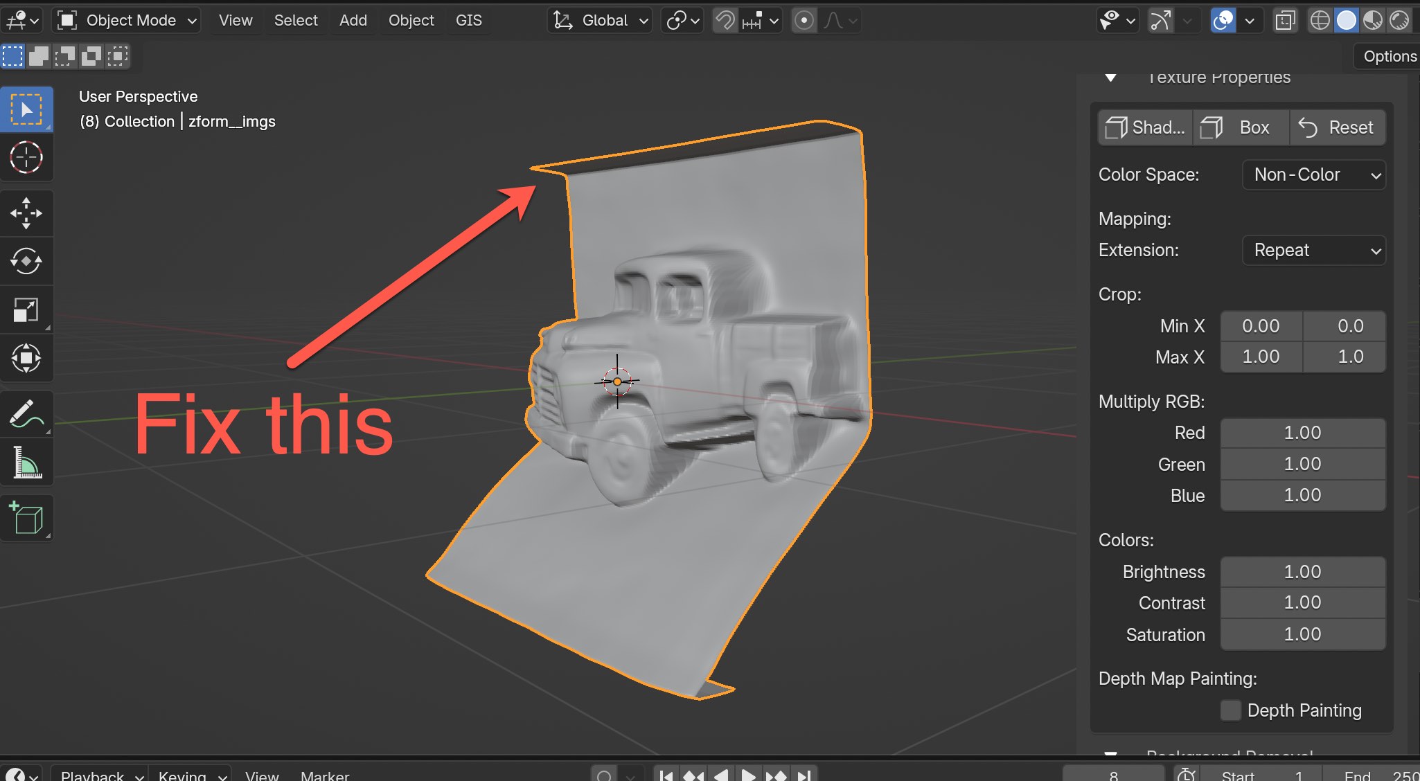
You can quickly fix this by switching to Extend.
Another interesting use-case is if you want a repeated grid of the same mesh like the example shown below. You can increase Crop values for Max X and Max Y by the same whole numbers from 1 to 3 to get a 3x3 grid.
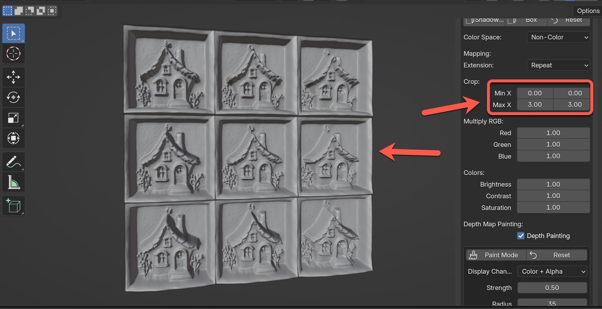
There's actually a lot more that can be achieved using different mapping extension options that I plan to cover with more examples in the future.
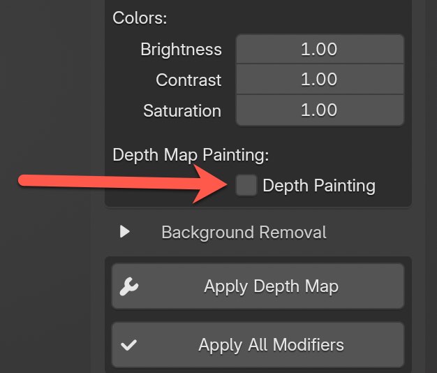
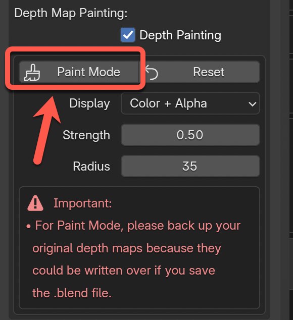
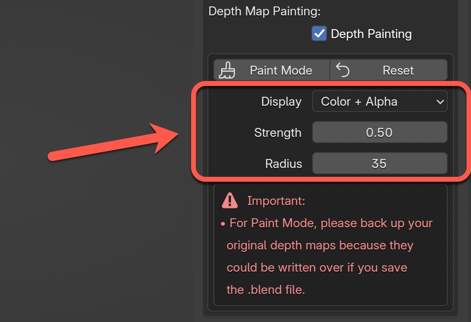
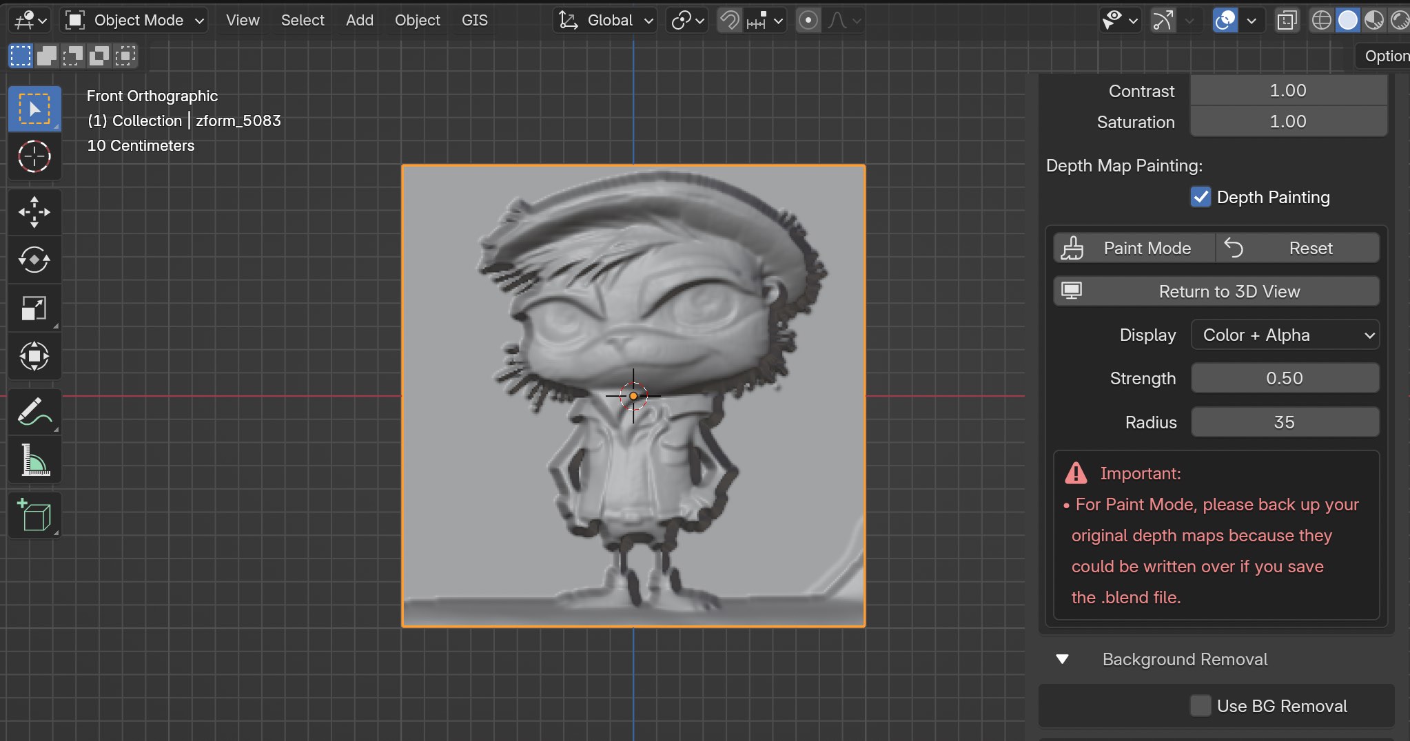
Depth Map Painting
One of the newest features released allows you to paint over an existing depth map and manually edit and refine depth maps directly within Blender's texture painting workspace. At any time you can switch back to the original depth map you used as the input.
IMPORTANT: To make the most out of Paint Mode, I recommend using Blender 4.3 or higher as there are more brush options available that are easily accessible.
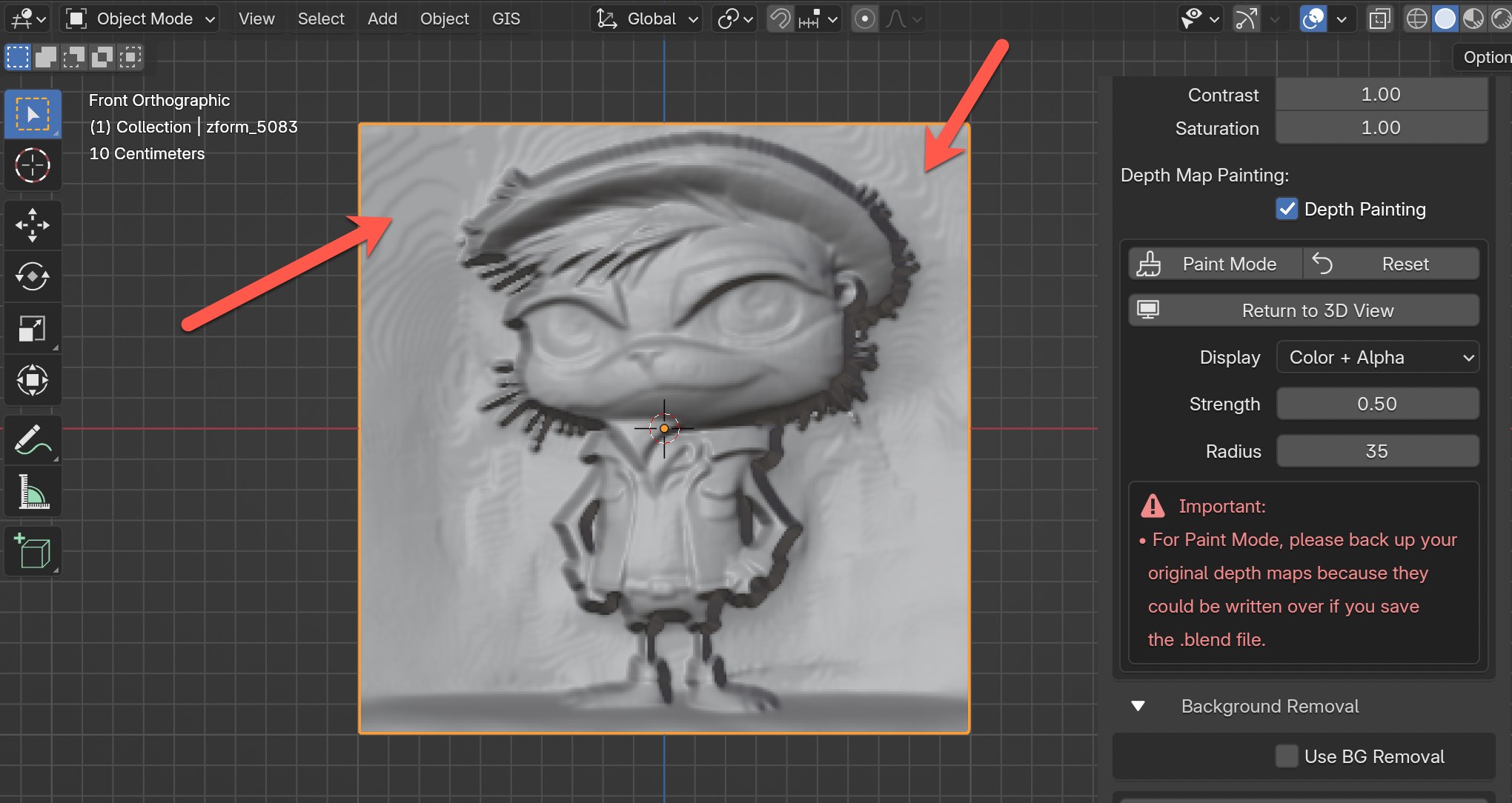
As a starting point, enable this feature by checking the box for "Depth Painting". It's important to point out that the feature isn't useable until you've already generated a 3D mesh using zForm's "Apply Depth Map" button.
IMPORTANT: Before trying out the Paint Mode feature, I strongly recommend backing up your original depth maps in an entirely separate directory with the depth maps being referenced in the tool. The reason is at this time, when you go into Paint Mode and edit the depth maps, it's editing the depth maps used as the original input depth maps. And if you end up saving the file, it will prompt you to save over and modify the initial depth maps.
Once enabled there will be options for Paint Mode, Reset, Display, Strength, and Radius.
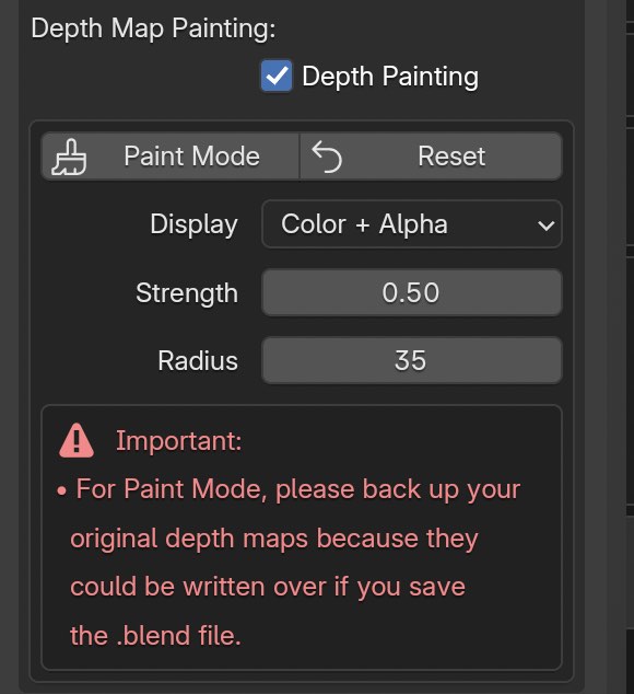
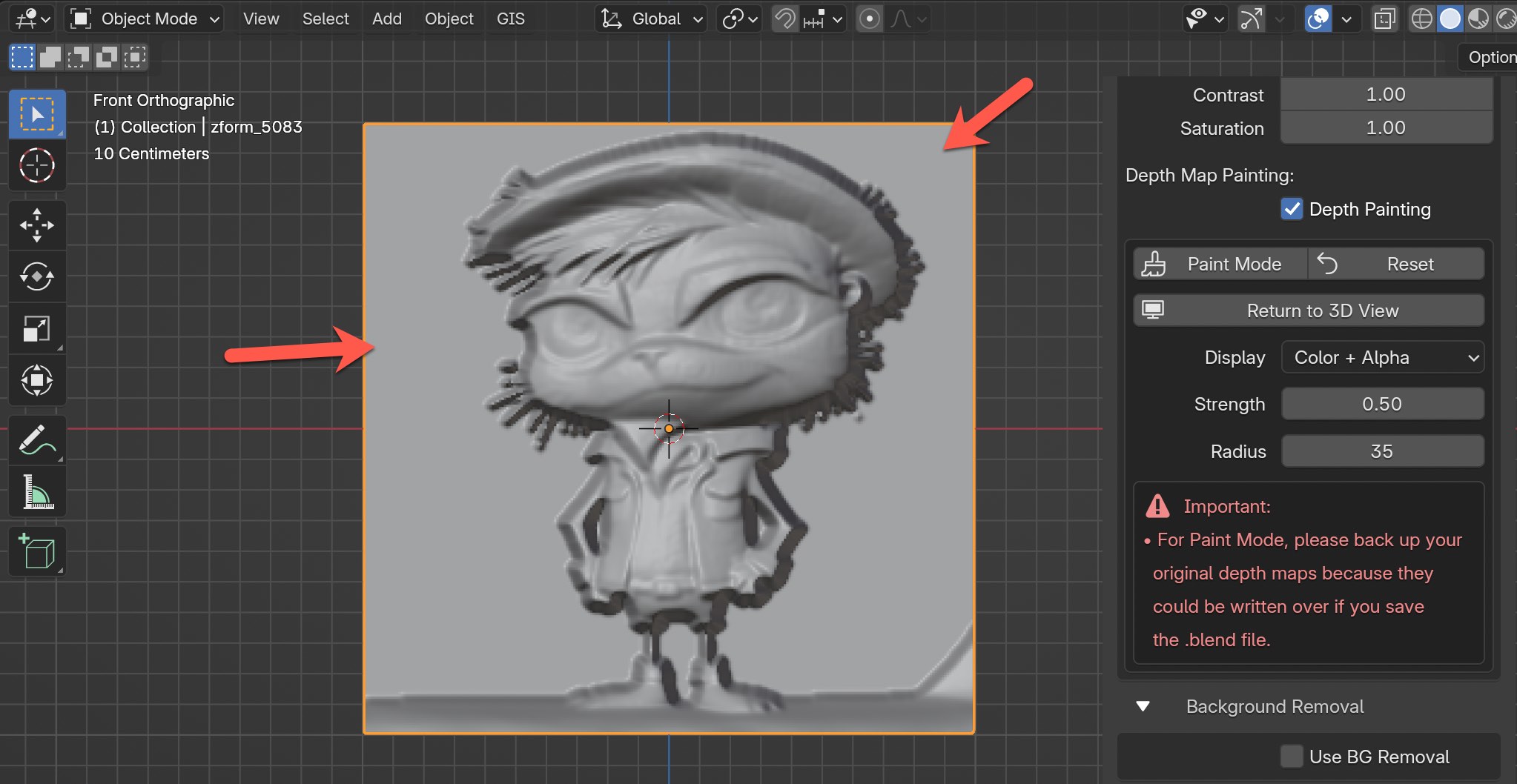
Now, click on the Paint Mode to get started.
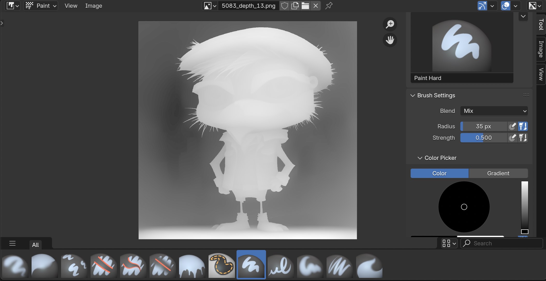
You'll be taking into what's called the Image Editor tool in Paint mode. At the bottom you'll see different brushes that can be used and on the right side there's a side-panel where a variety of adjustment options are available.
If you don't see the side-panel on the right side, type in the letter "N" on your keyboard to pull it up.
Next, just to get you comfortable with navigation and using Paint mode, let's exit the Paint mode entirely to go back to the screen we were previously in 3D Viewport.
To do that, go to the top left and click on the 3D Viewport option.
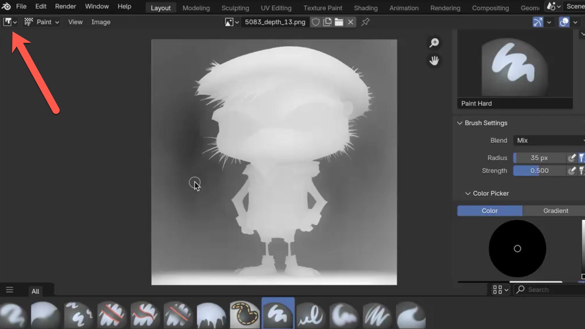
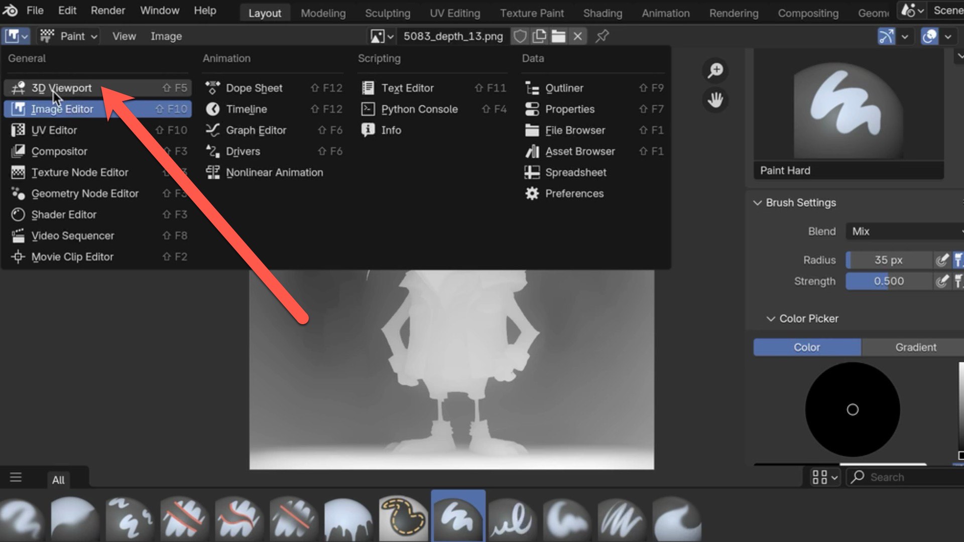
This will take you back to where we were before. Each time you're finished with working in Paint Mode, this is how you can get back to the main work area in 3D Viewport.
The three options available for Display, Strength, and Radius can also be adjusted in the Paint mode as well.
For Display Channel, this functionality is useful for fine-tuning and inspecting specific aspects of your depth map, such as texture details and transparency. Here's a brief summary of each option:
- Color & Alpha: Shows the full composite image with both color (RGB) and transparency (alpha) information.
- Color: Displays only the color channels, ignoring any transparency.
- Alpha: Reveals just the alpha (transparency) channel as a grayscale image.
- Red, Green, Blue: Isolates each individual color channel, showing its intensity in a grayscale view.
Whereas the Strength and Radius adjustments are specifically for adjust the brush strength and radius.
Okay, let's try a few brush in Paint mode techniques. Please keep in mind the techniques I share don't always work...it's a case-by-case basis and really depends on the depth map.
For the first example, take a look at the unwanted ridgelines in this mesh that can occur sometimes when using 8-bit depth maps for background areas. We're going to use the Fill brush to smooth out the backside and remove those unwanted areas entirely.
The final result for this example looks like this. See how flat the background is?
In Paint mode, click on the Fill brush.
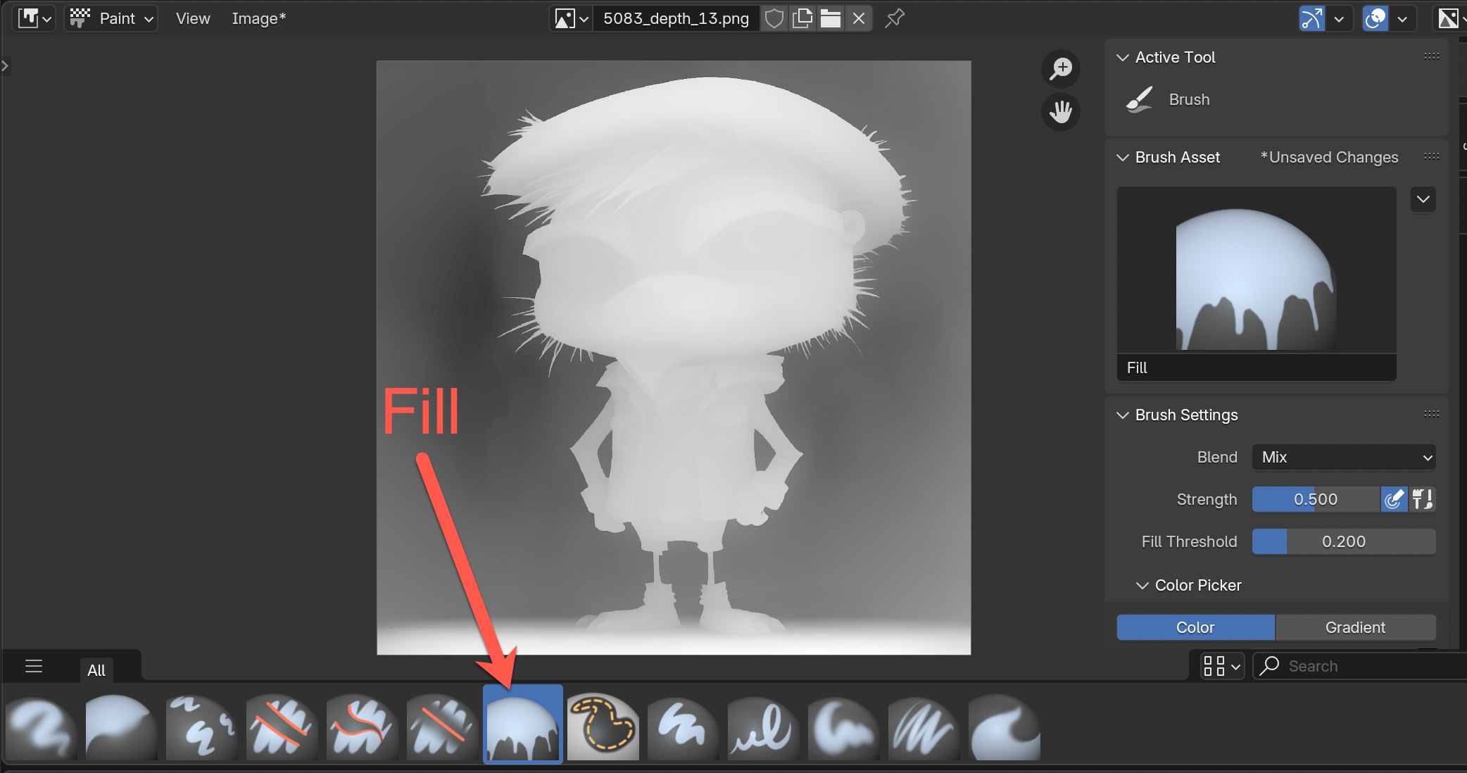
Next, start clicking on the outer background area of the depth map where it's very evident it's the background. Try clicking once to start with and then keep clicking. You'll see that each time you click more of the background is being filled until finally it turns completely black.
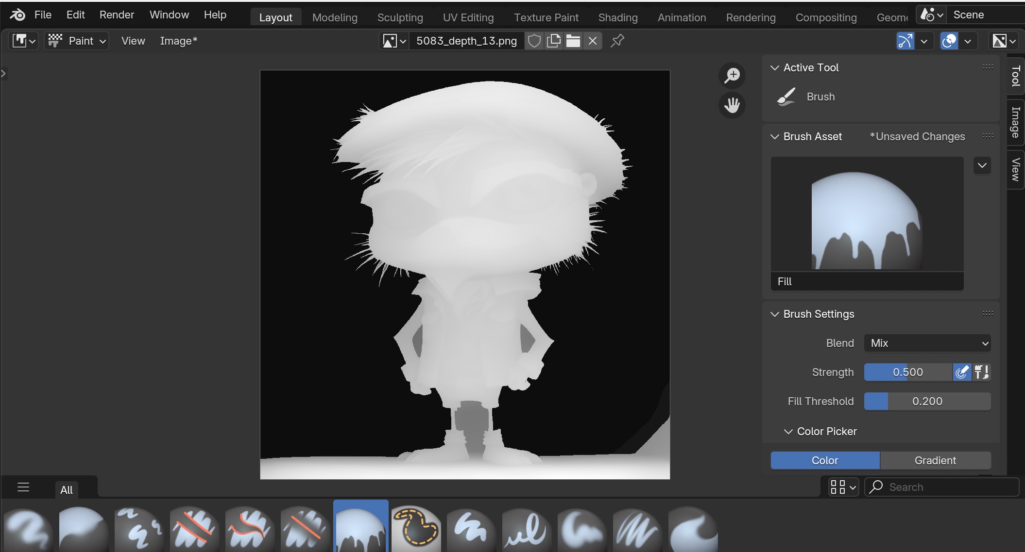
Also, if you have other tiny areas that are separate than the background like the ones called out below, you can try filling those as well.
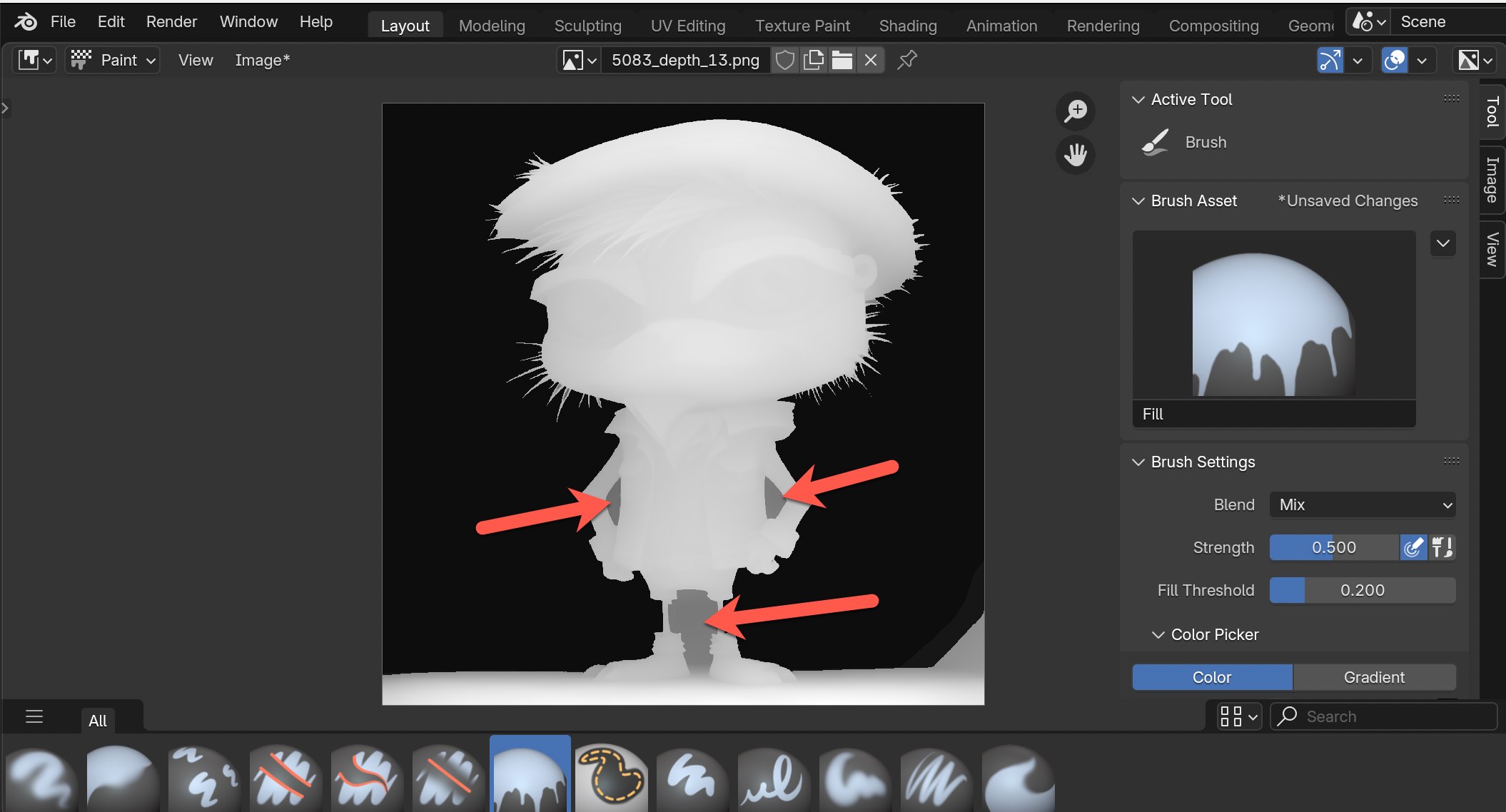
Here's the result.
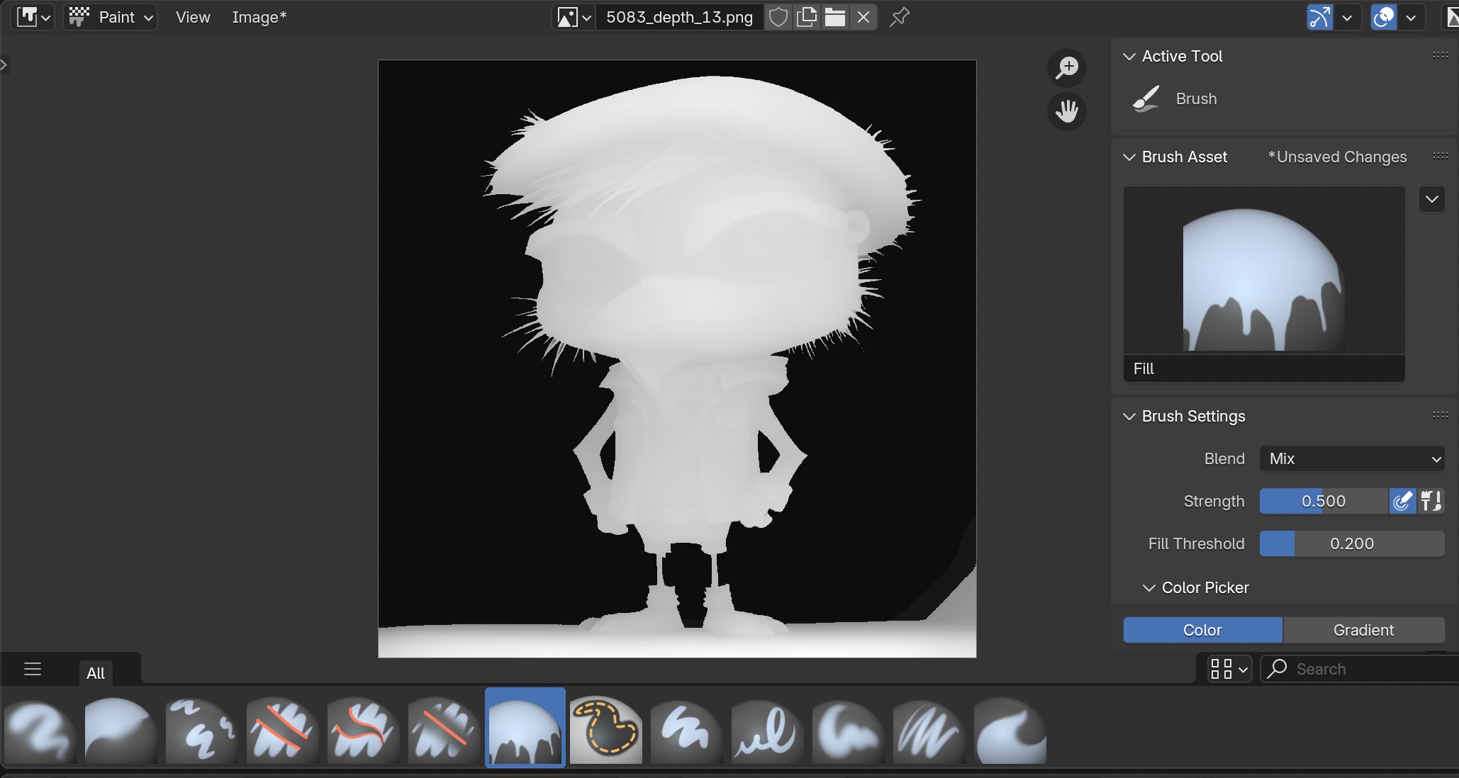
Next,let's take a look in the 3D Viewport. Remember to switch back in the top left.
Here are the results. This can be quite effective where the backside of the depth map is distinctively different than the foreground.
Alright, let's try another one. Go back into Paint Mode again and choose the Erase Hard brush.
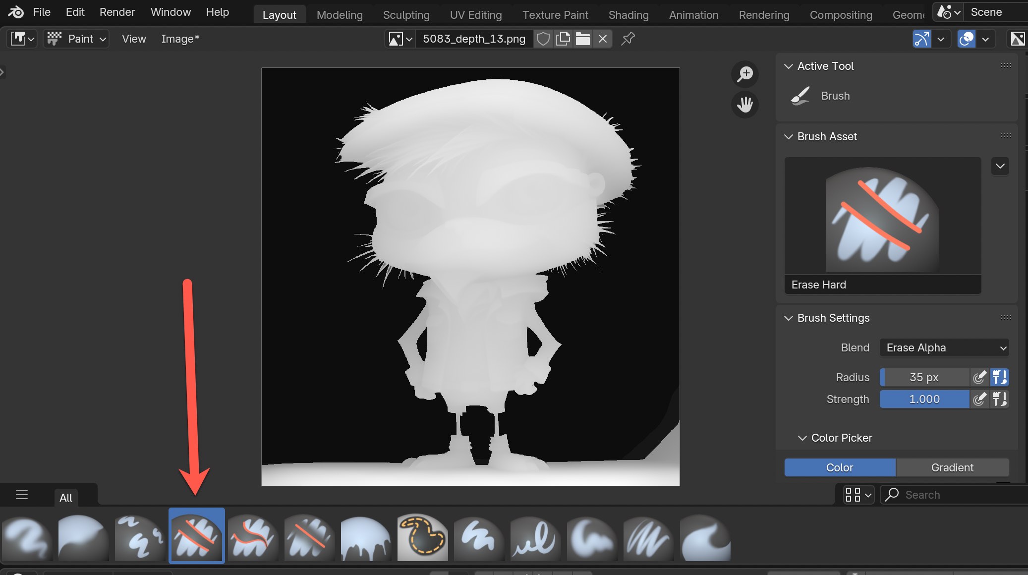
Try applying the brush around areas of the depth map for objects that are closest to the camera view like this.
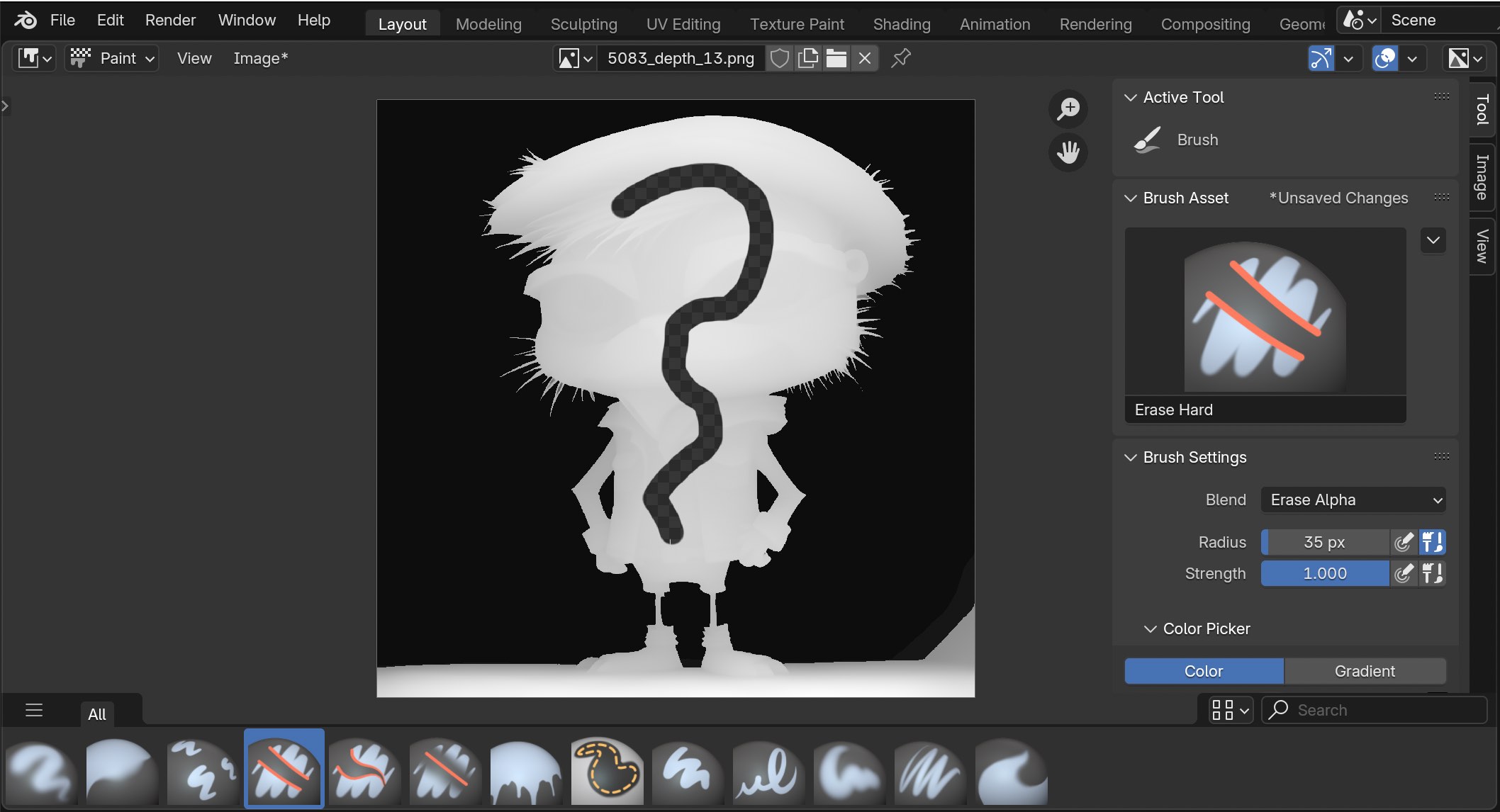
Now go back into 3D Viewport to take a look. We erased parts of the depth map and here's the results for this example.
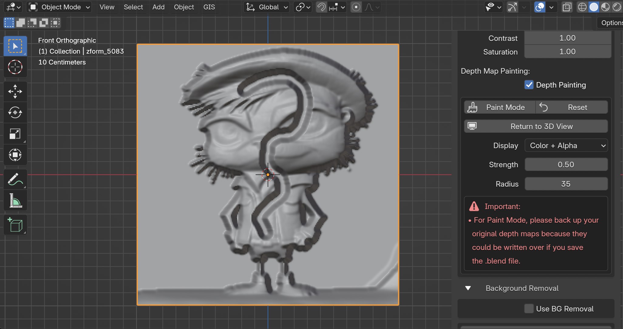
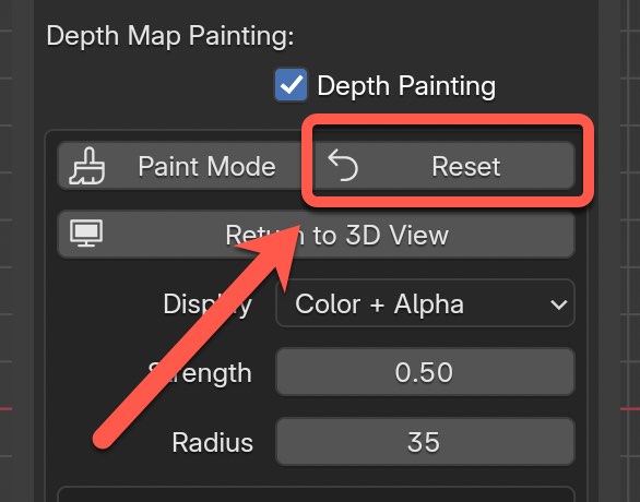
Lastly, if you ever want to reset to go back to the orininal depth map all you need to do is click on the Reset button in the top right.
I hope these examples help get you started. There are several different brushes and display channels you can experiment with. I plan to have more documentation and add more examples in the future for the Paint mode.
Background Removal
There are a few different techniques to remove the entire backside of a mesh and it depends on what the initial mesh looks like to begin with.
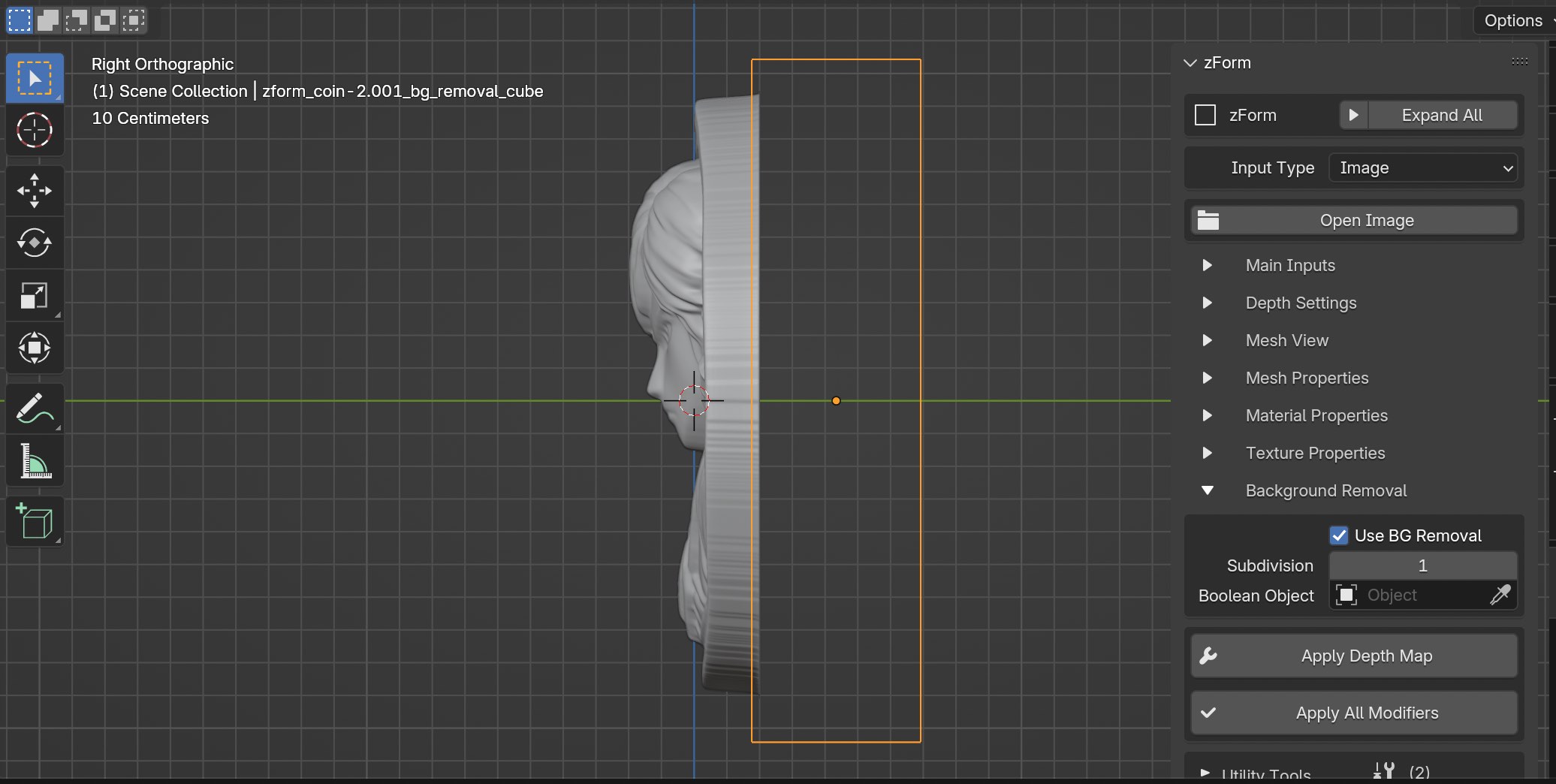
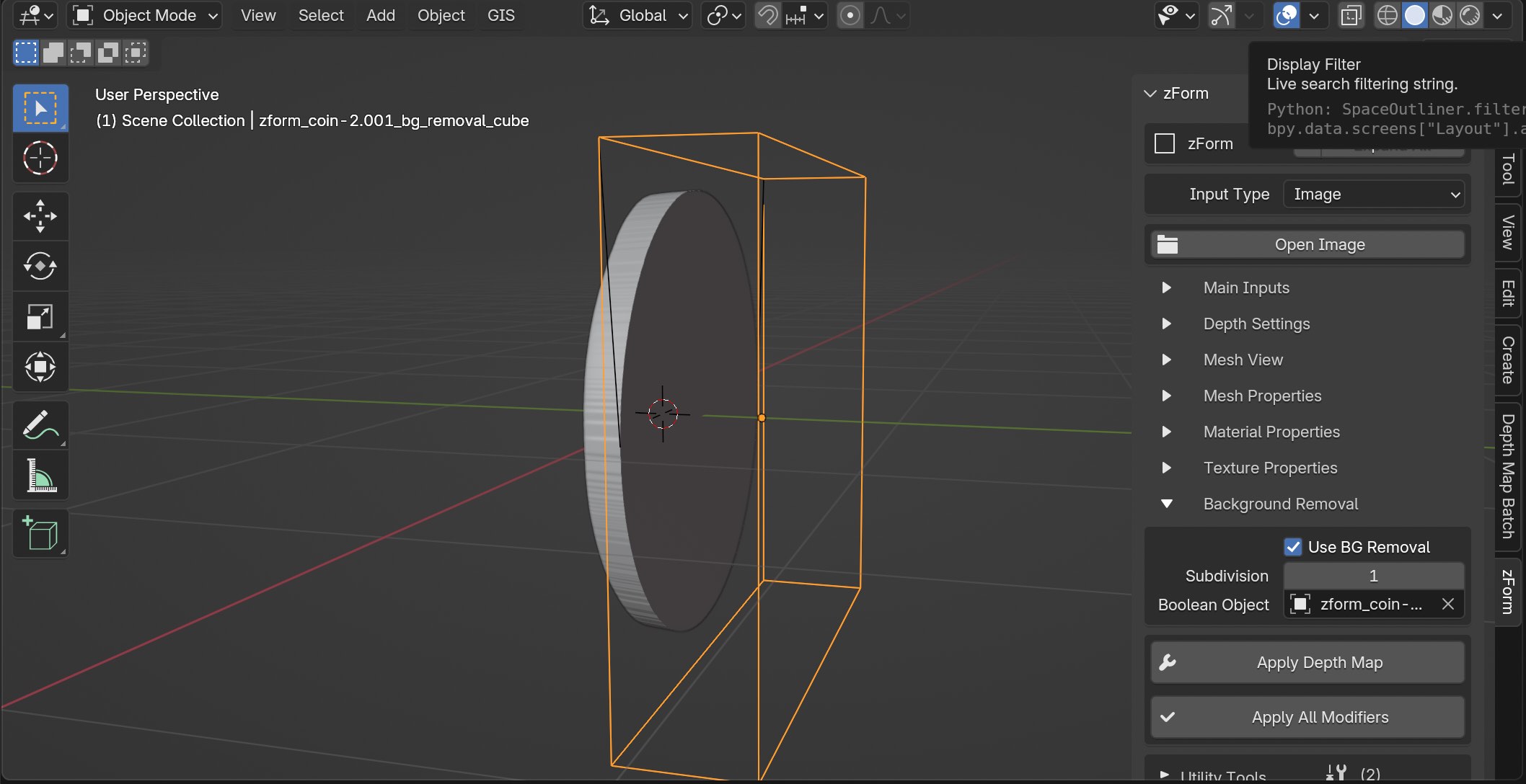
We'll start with the easiest example for this coin. You'll notice that none of the edges of the coin touch any of the outer edges of the mesh. I'll also cover one other example and technique after this one.
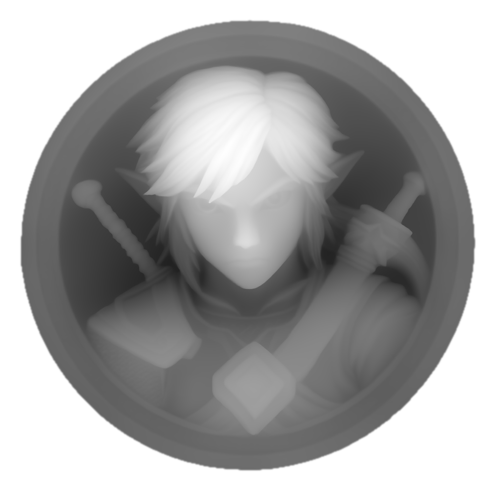
And for reference, here's what the original depth map looks like. If you have the ability to produce a depth map that has a tranasparent background that can help improve results of the mesh and displacement, but if not that's fine too.
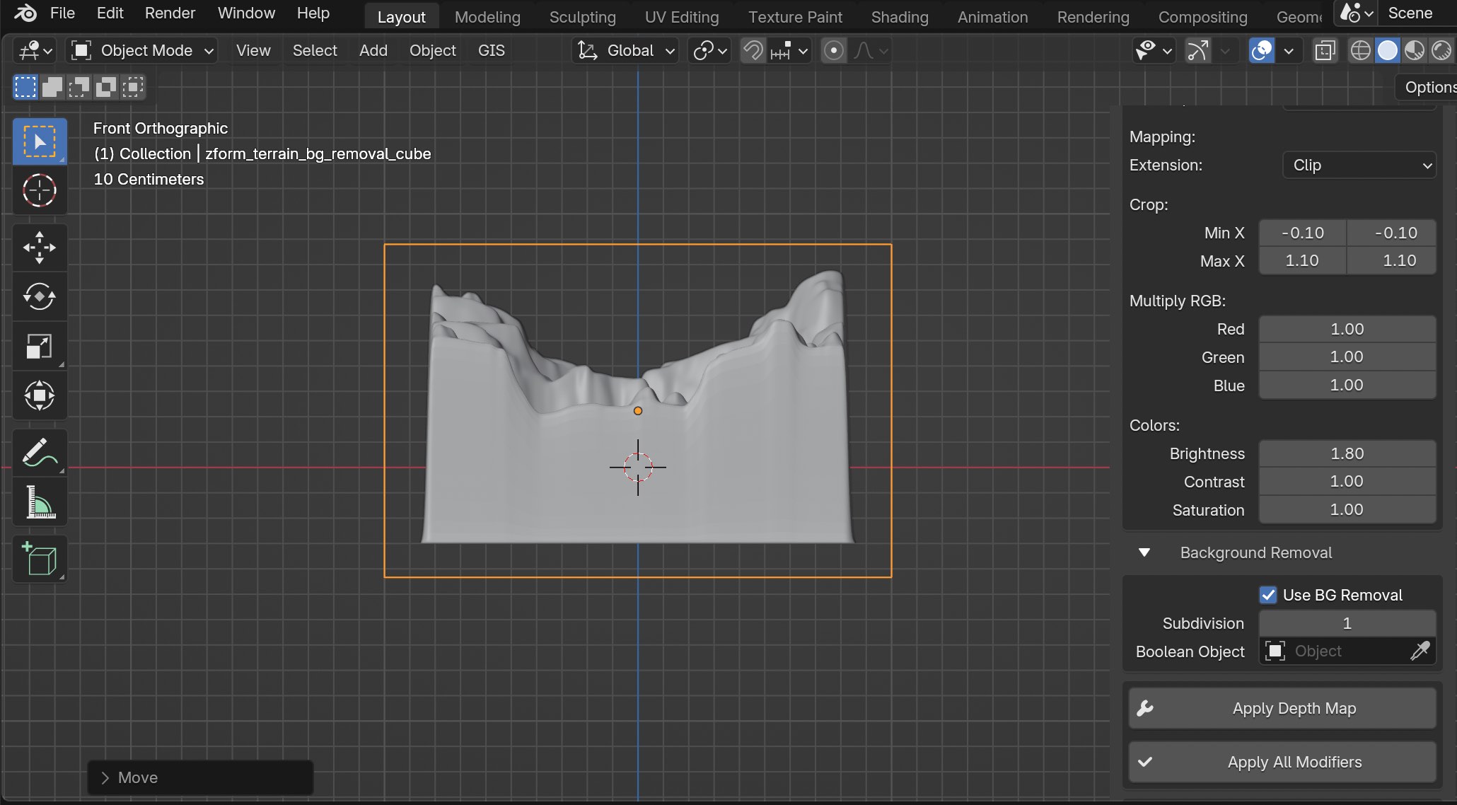
Go down to the bottom section called "Background Removal" and enable the "Use BG Removal" feature. You should now see a new empty cube that surrounds your mesh. Leave the Subdivision value at 1.
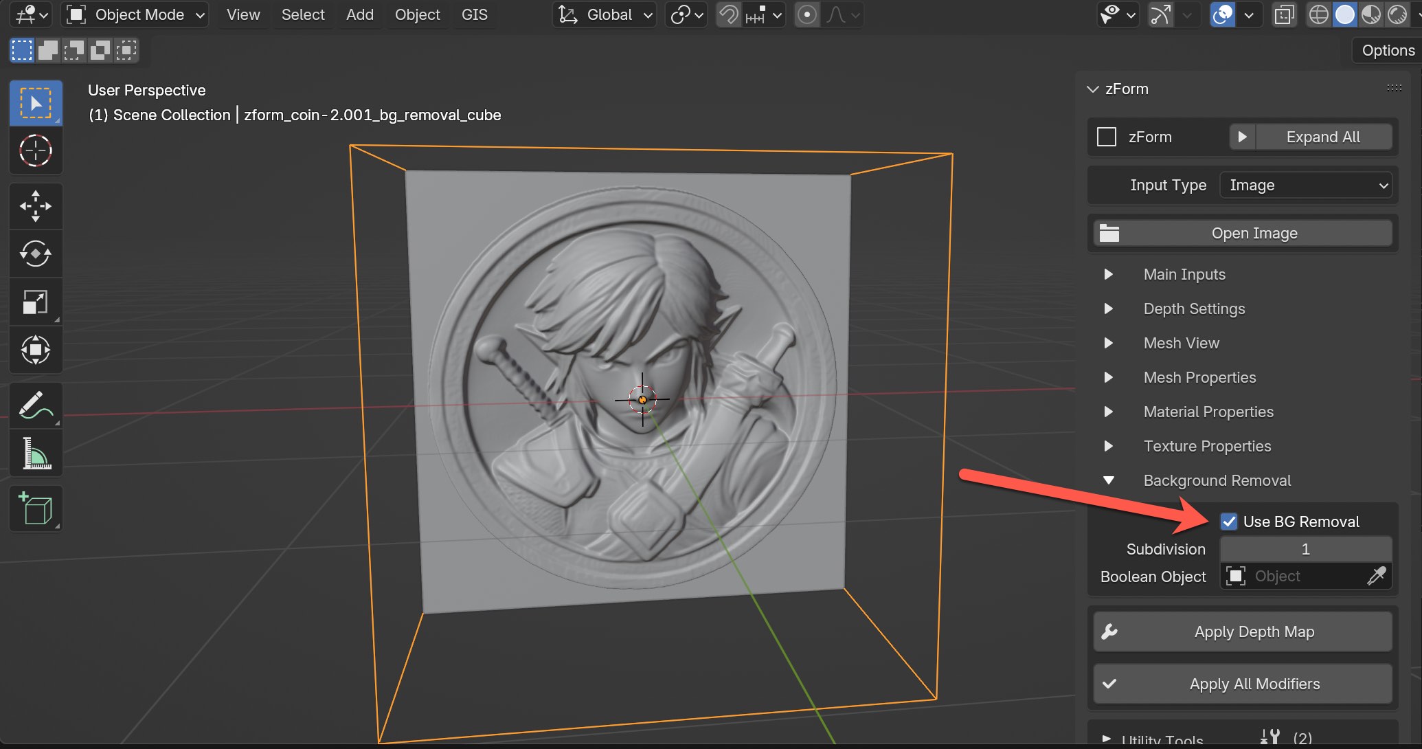
The main objective is to use the empty cube to cut out the entire backside of the mesh. Whatever is contained within the empty cube will be removed.
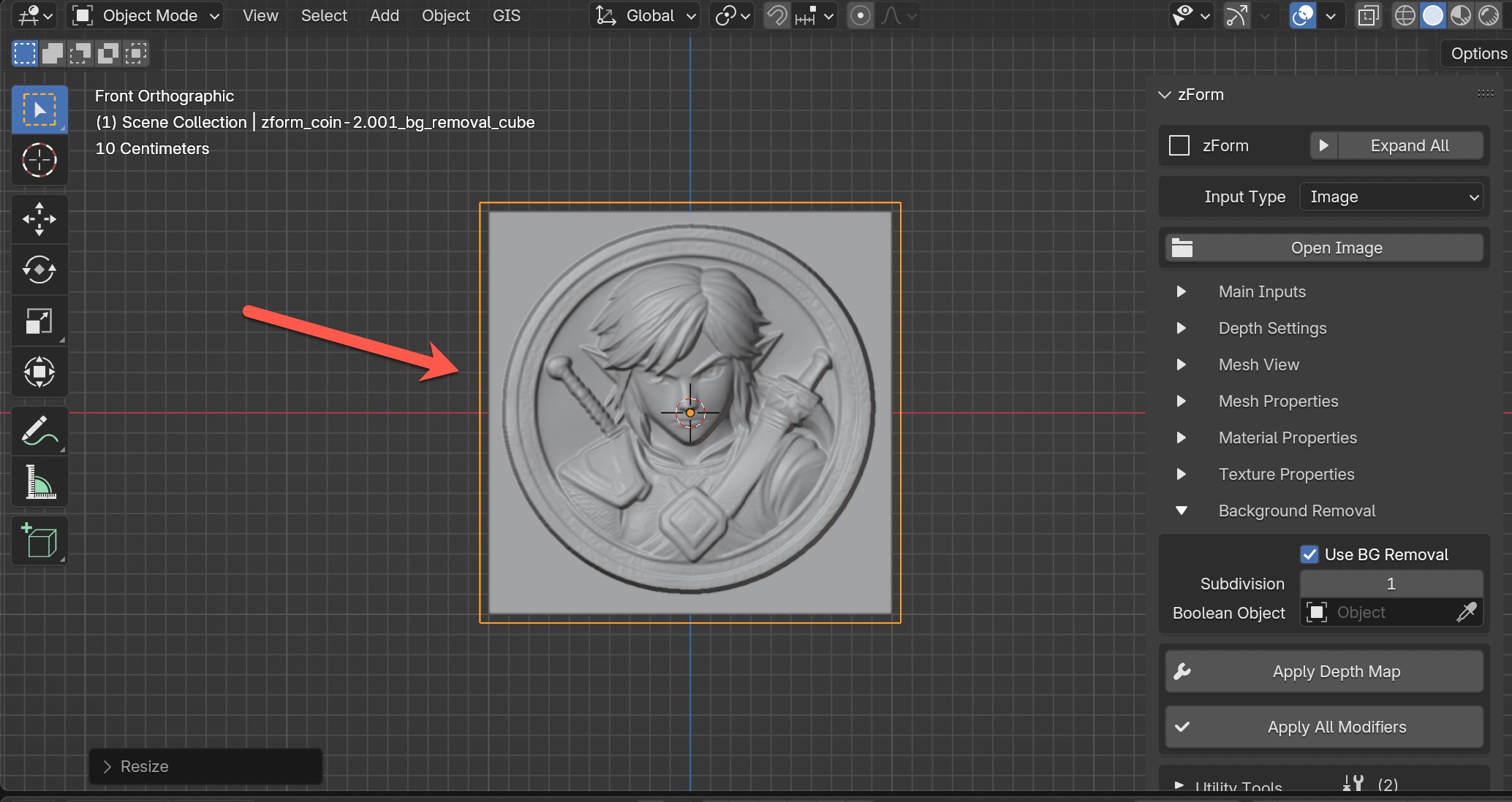
Select the empty cube and scale the object so that it fits fully outside of the original mesh for the front view. You can see in the example below that I've scaled the cube to be slightly bigger than my mesh.
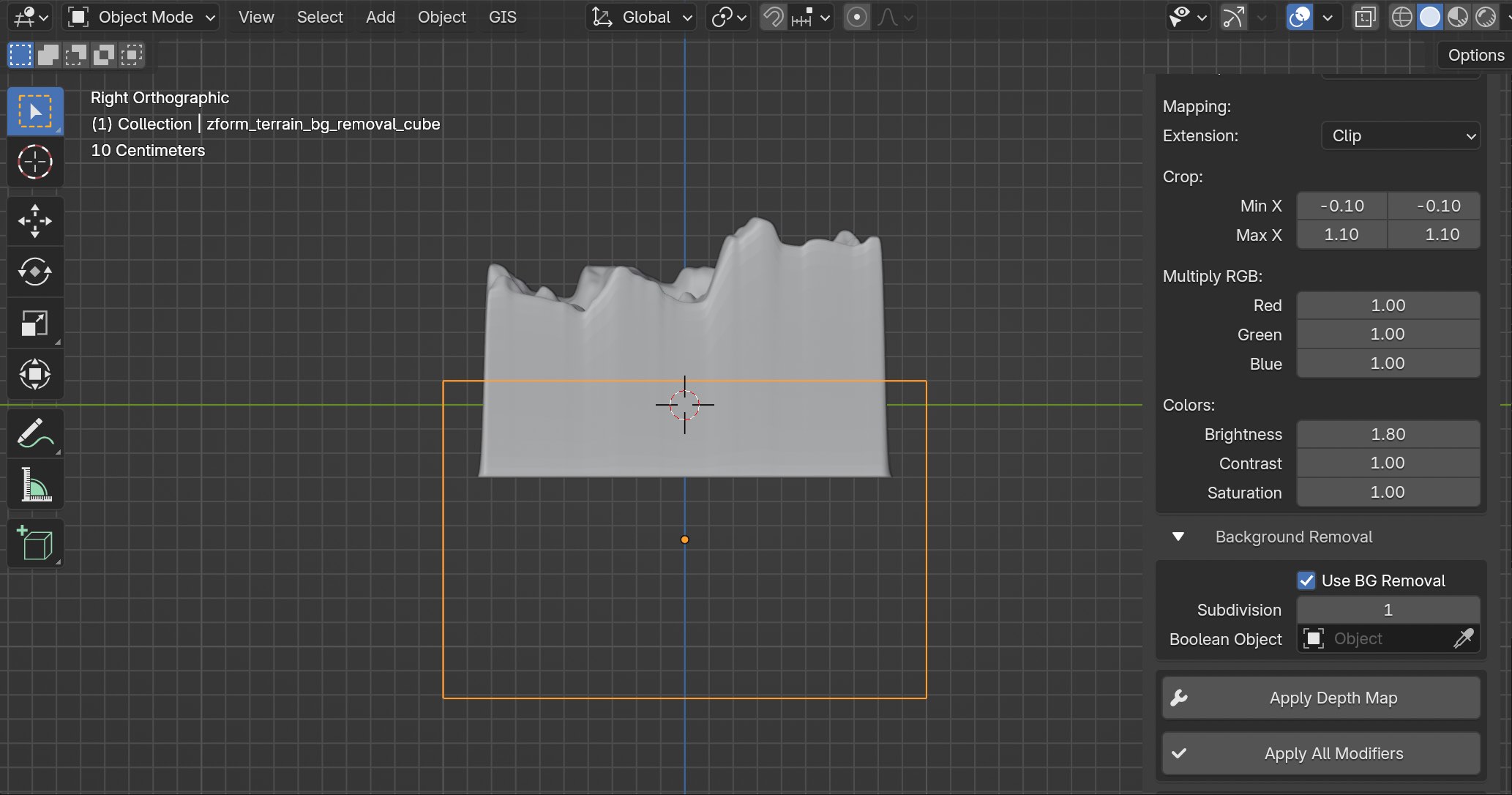
Now go into the side view and adjust the empty cube so that it covers only the very back side, while the remaining part of the mesh is outside of the cube. I will typically scale down the empty cube along the Y-axis to make it smaller. It might be difficult to see here, but the empty cube is barely capturing the back side.
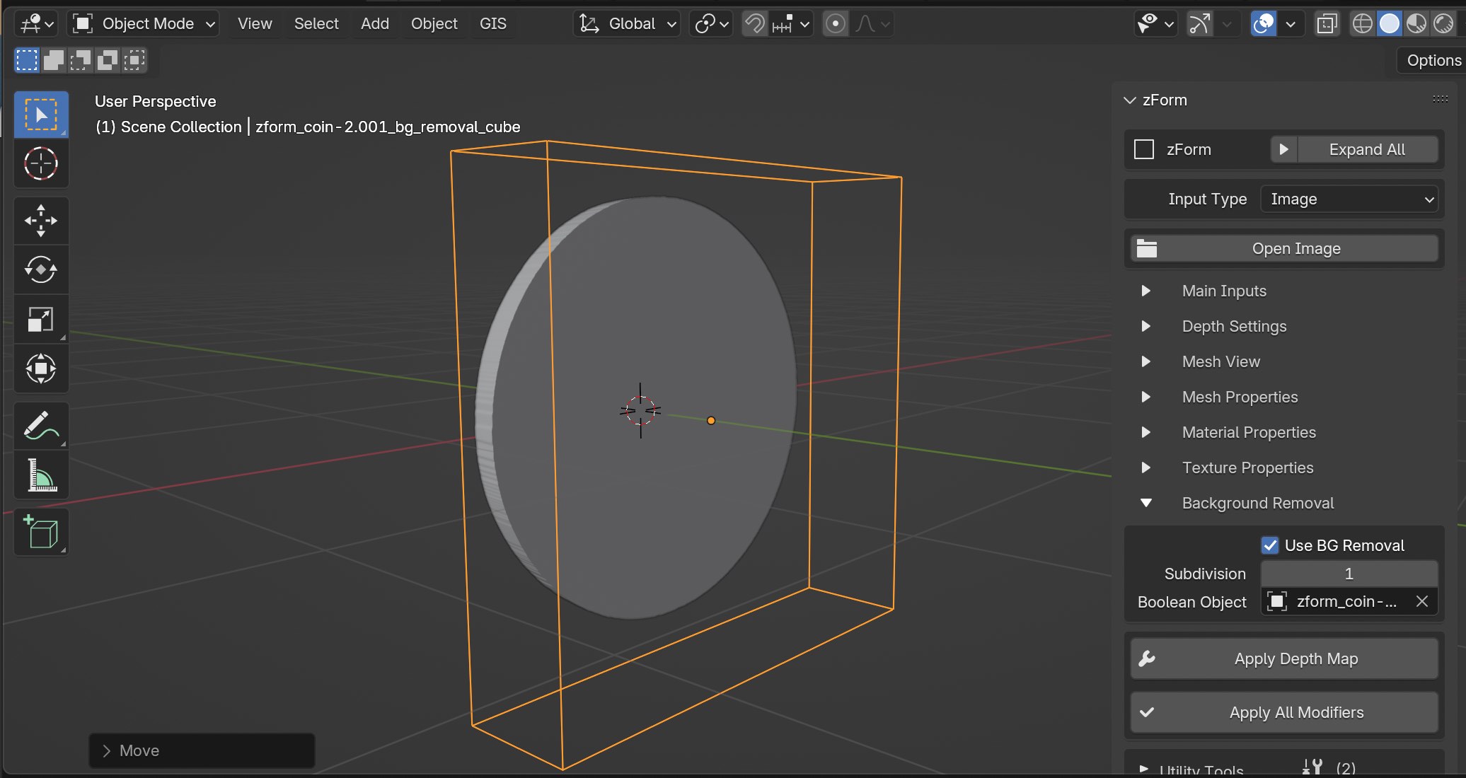
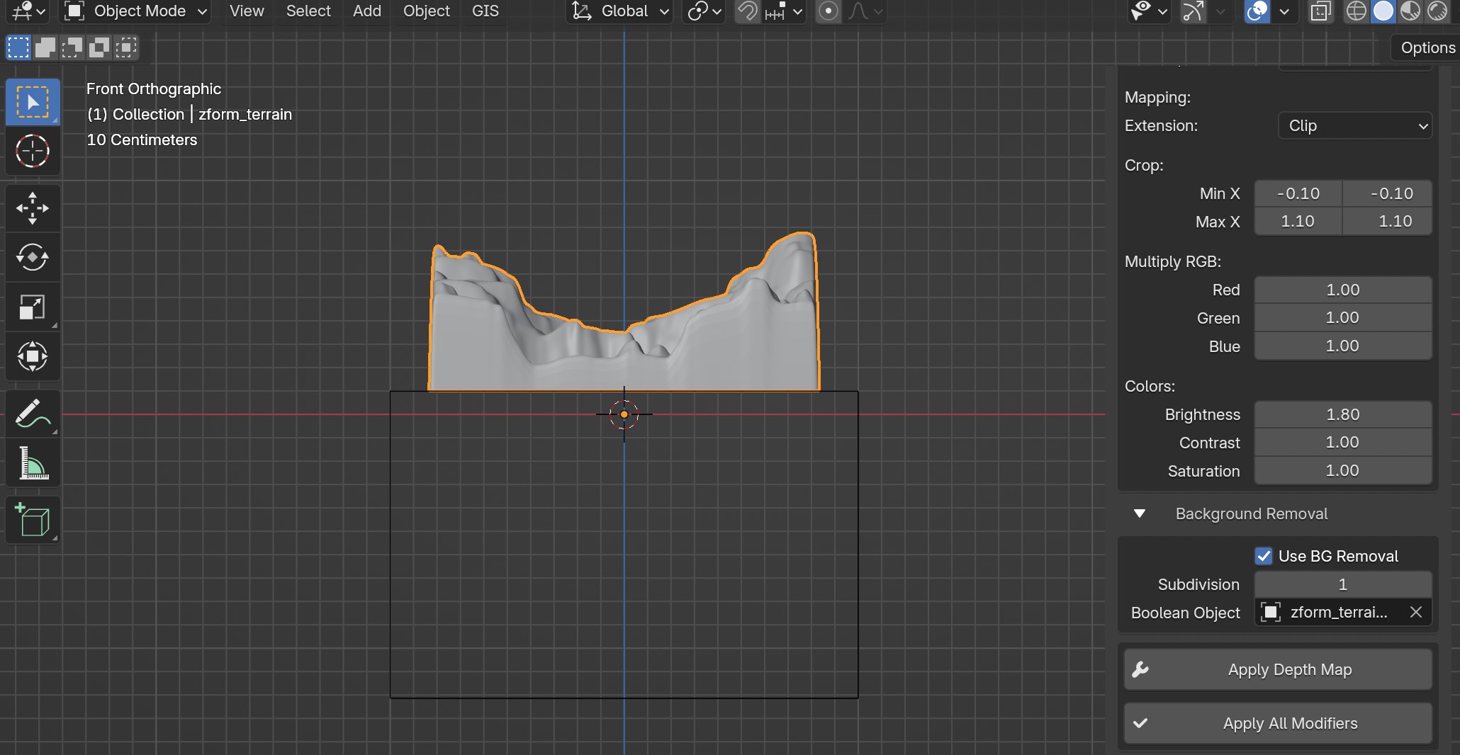
Then, I will go back to front view and make sure to click back on the original mesh.
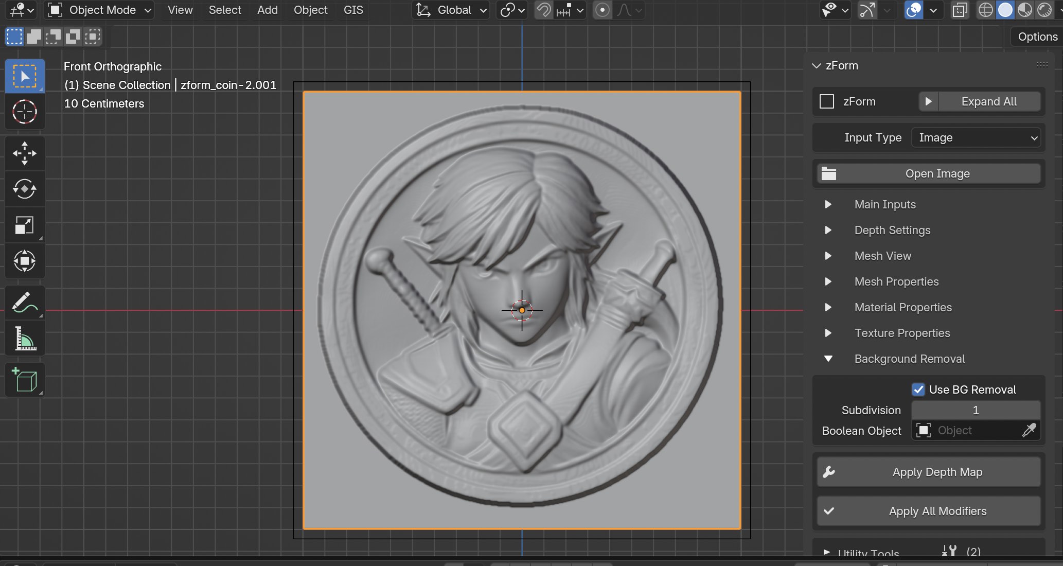
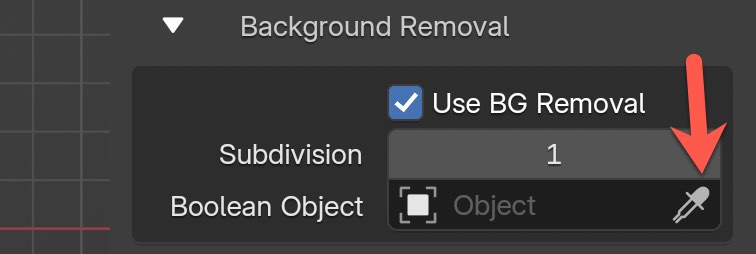
The very last step is using the eyedropper for the Boolean Object field and choosing the empty cube.
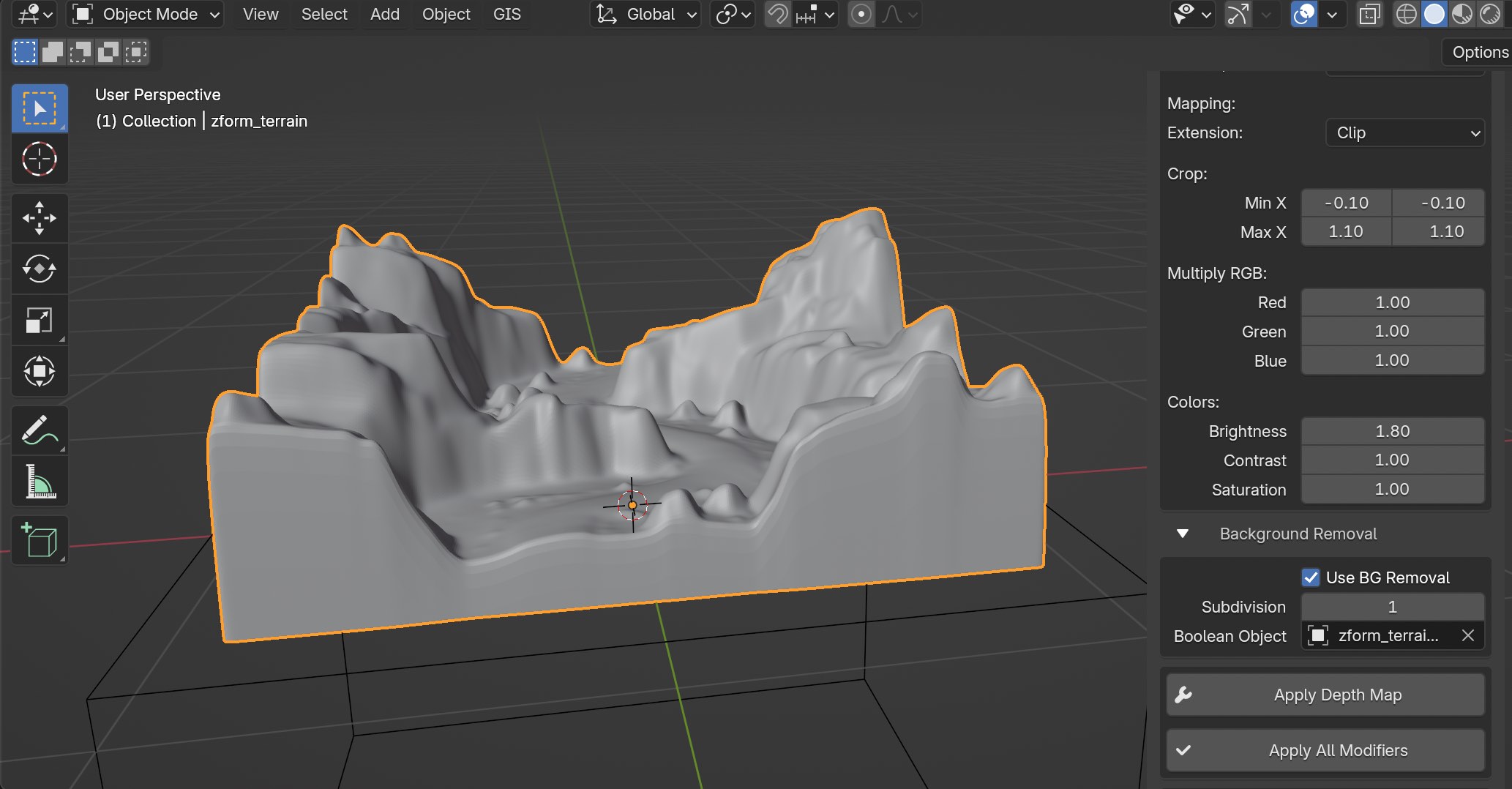
You should now see the backside of the mesh removed. It might take a few tries to move around the empty cube so that it fits nicely to get a clean removal. In this example there are a few outlier artifacts with those two lines, but we'll take a few more steps to remove them.
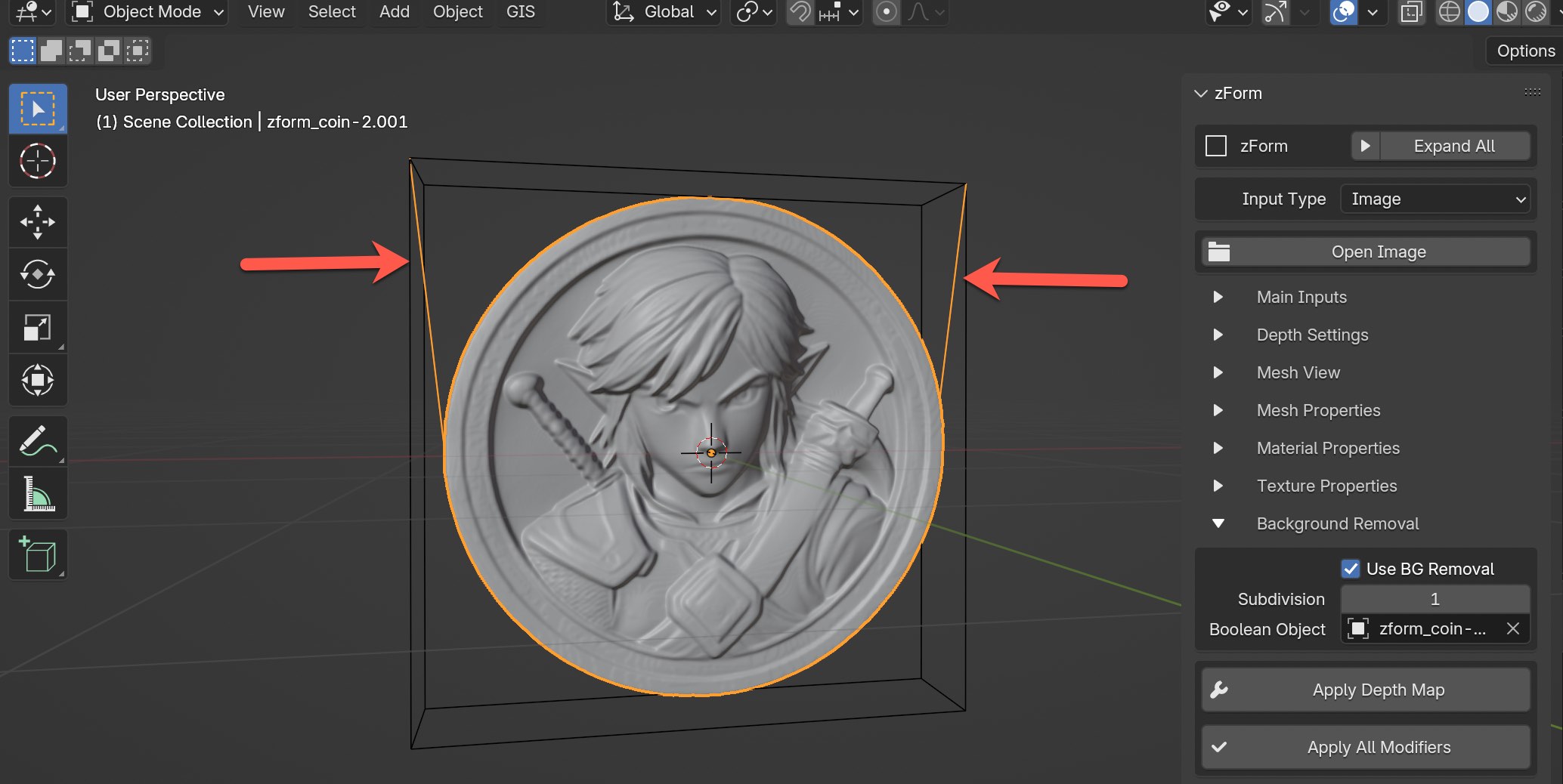
Now select the empty object and go into the side view again. Get set up at an angle so you can see both the backside of the mesh and also be able to monitor when the outlier artifact edges are removed.
I will then proceed to move the empty cube forward very slightly along the Y-axis. Move in tiny steps. Depending on how dense your mesh is with the subdivision levels, it could be a little slow. But, ultimately you want to align the cube until has a clean cut. You might even need to try moving the empty cube back along the Y-axis instead of forward.
Go back into front view again and take one more look to make sure everything looks good.
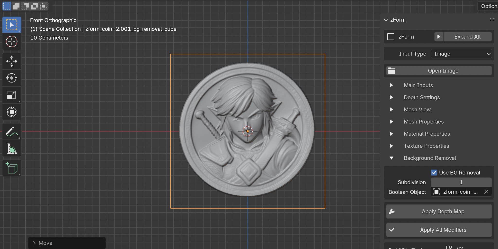
The good thing about this technique is it's non-destructive so you can go back at any time to fix possible issues.
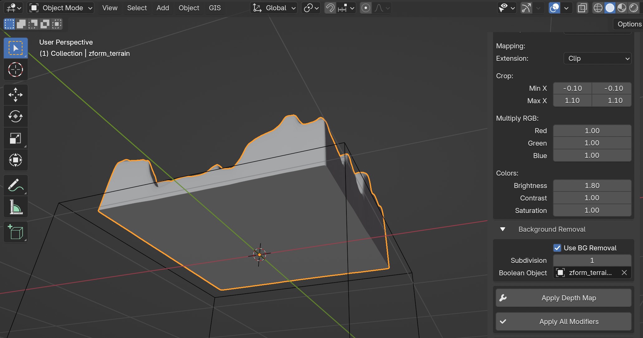
Let's try a different example for some terrain shown below. In this use-case the main object has parts touching the outer edges of the mesh. To remove the backside of the mesh we need to handle the technique a little differently.
Go to the Texture Properties section and click on the "Box" icon to create a box for the mesh with thickness. At any time you can adjust the Depth Strength or Brightness values to increase or or decrease the box thickness.
Next proceed with enabling the "Background Removal" feature that we covered in the previous example. We'll follow with the same steps now with how we handled the last one. I scaled down the empty cube to fit slightly larger than the main object.
I'll now go into side view to adjust the positioning and scale along the Y-axis for the empty cube. In this case the terrain is facing on top, so I positioned the empty cube to be on the bottom.
Last make sure to select your original object again and click on the eye dropper tool in the Boolean Object section. That should be it! Of course you might need to adjust the positioning of the empty cube to get it right, but it typically doesn't take very long at all once you practice a few times.
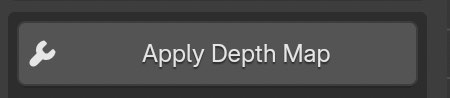
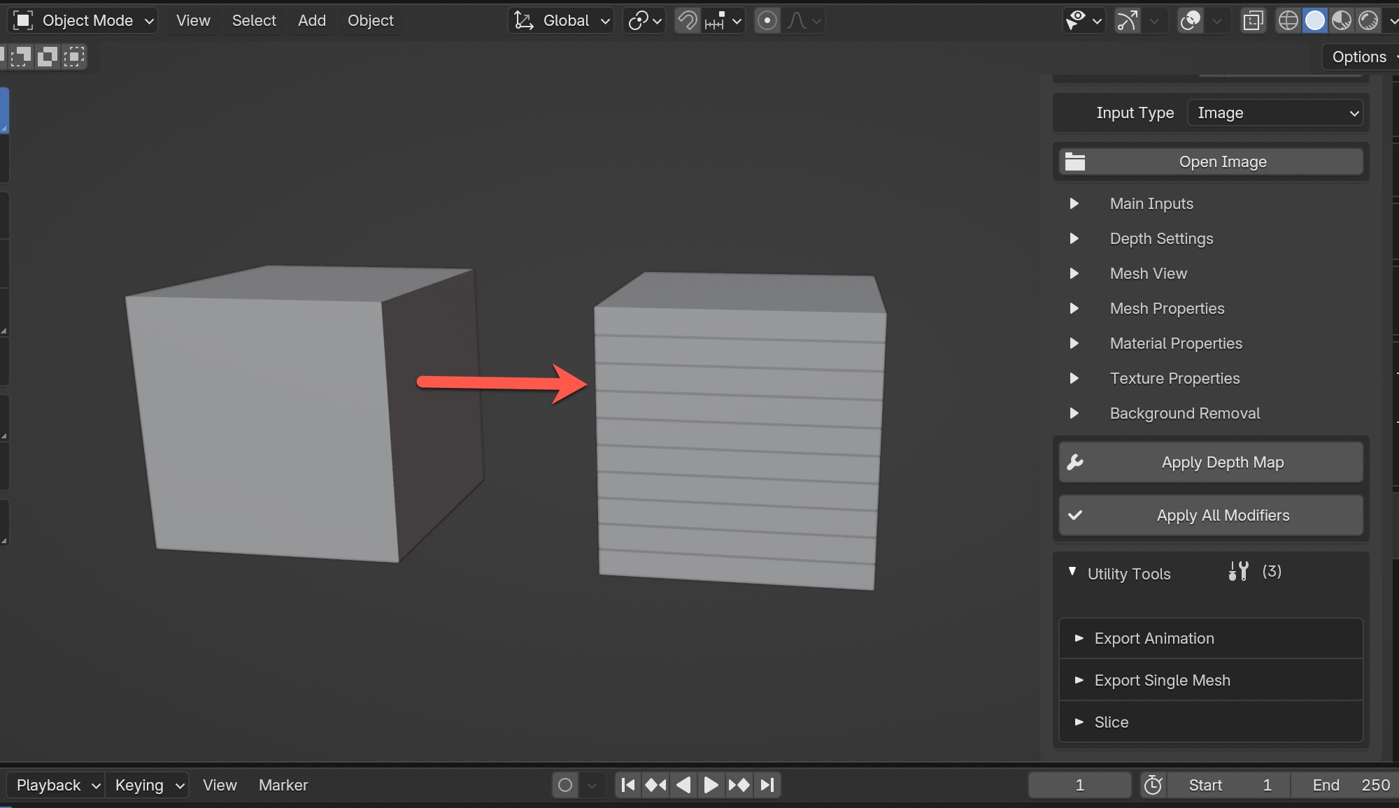
Apply Depth Map
Once you're ready to generate the initial geometry and mesh for the depth map you will click on this button. Because modifiers are non-destructive in nature, you can change any values for fields in the main section of zForm and the mesh will adjust in real-time.
Most of the time I will start out by quickly going to this step to generate the initial mesh, and then afterwards I'll adjust parameters as needed. I find this to be an efficient workflow. Also, I rarely use a Subdivision Level value above 8 on the very first mesh generation because it will slow down performance when making edits. Only at the very end when everything is ready to go that I will consider increasing the sub-division level if my depth map is high enough quality to do so, otherwise I will just leave the subdivision at 8.
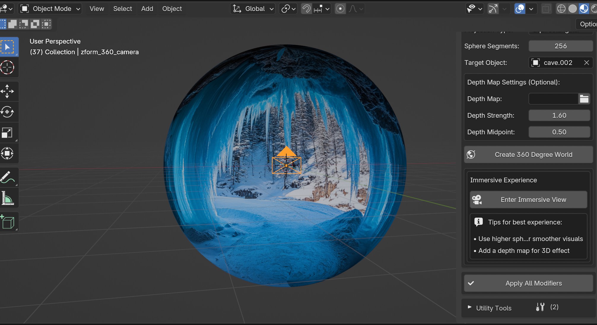
Create 360 World
This button for Create 360 World is only usable for the Explore 360 input type and is used to turn your static flat image into an immersive sphere that can be explored.
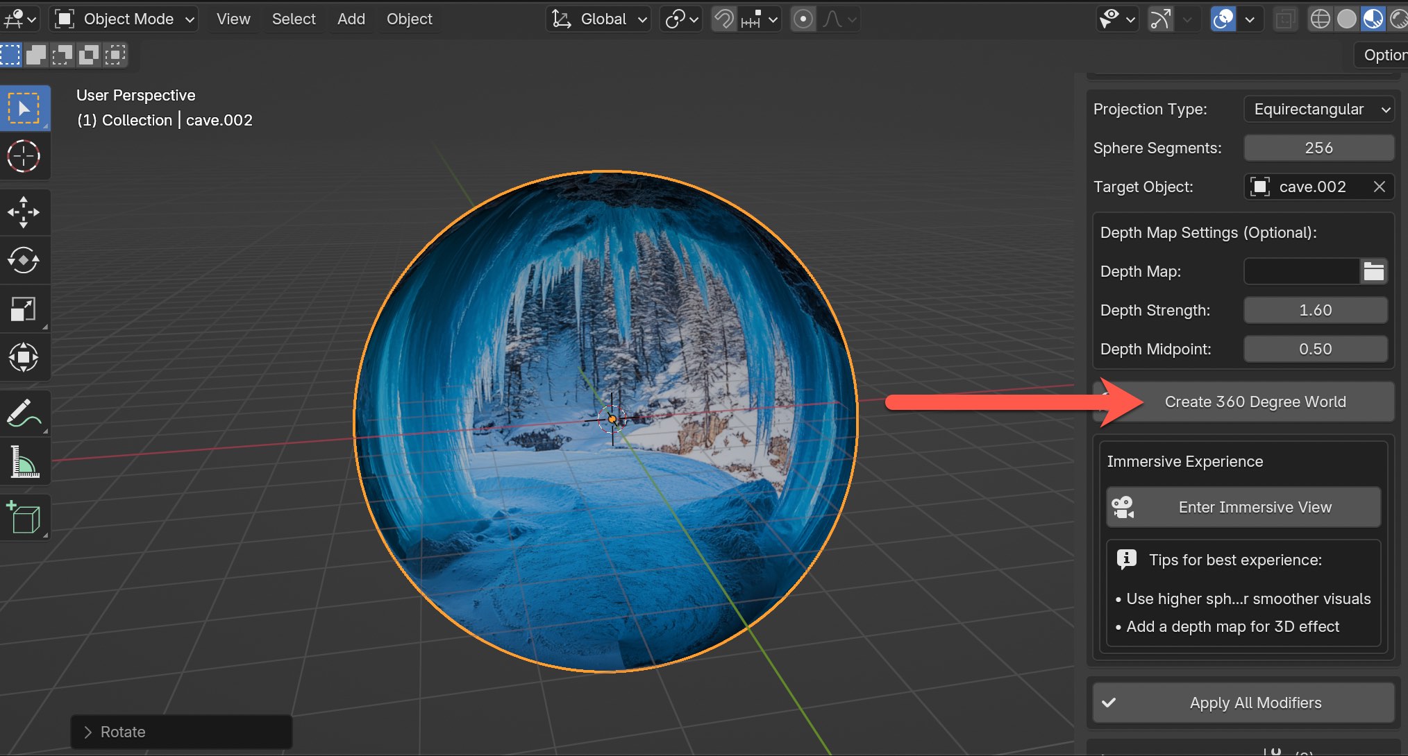
One you click on the button your image should now look something like this if you go into Material Preview mode.
Apply All Modifiers
Button to apply all modifiers to the mesh, which will make it destructive and you can't change after unless you undo immediatelly after applying modifiers. This step can be beneficial if you need to do some cleanup or edits to the mesh.
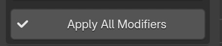
For very dense mesh that has a subdivison level above 8 it can take some time to finish, so please be patient.
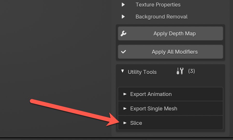
Utility Tools
At the moment there is two main utility tools named Export Animation to export animated mesh to a GLB/GLTF file format, but as I plan to release new utility tools in the future. There is a second section titled Export Single Mesh that covers the important steps in exporting a mesh, but it's not currently a tool per say.
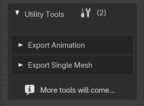
Export Animation
A powerful tool that will allow you to export an animated mesh that can be generated from either using the Video or Directory input types. Either one will produce animations with having one mesh per frame in a sequence. What's important to note is for both examples when the mesh changes on each frame it's still one single mesh.
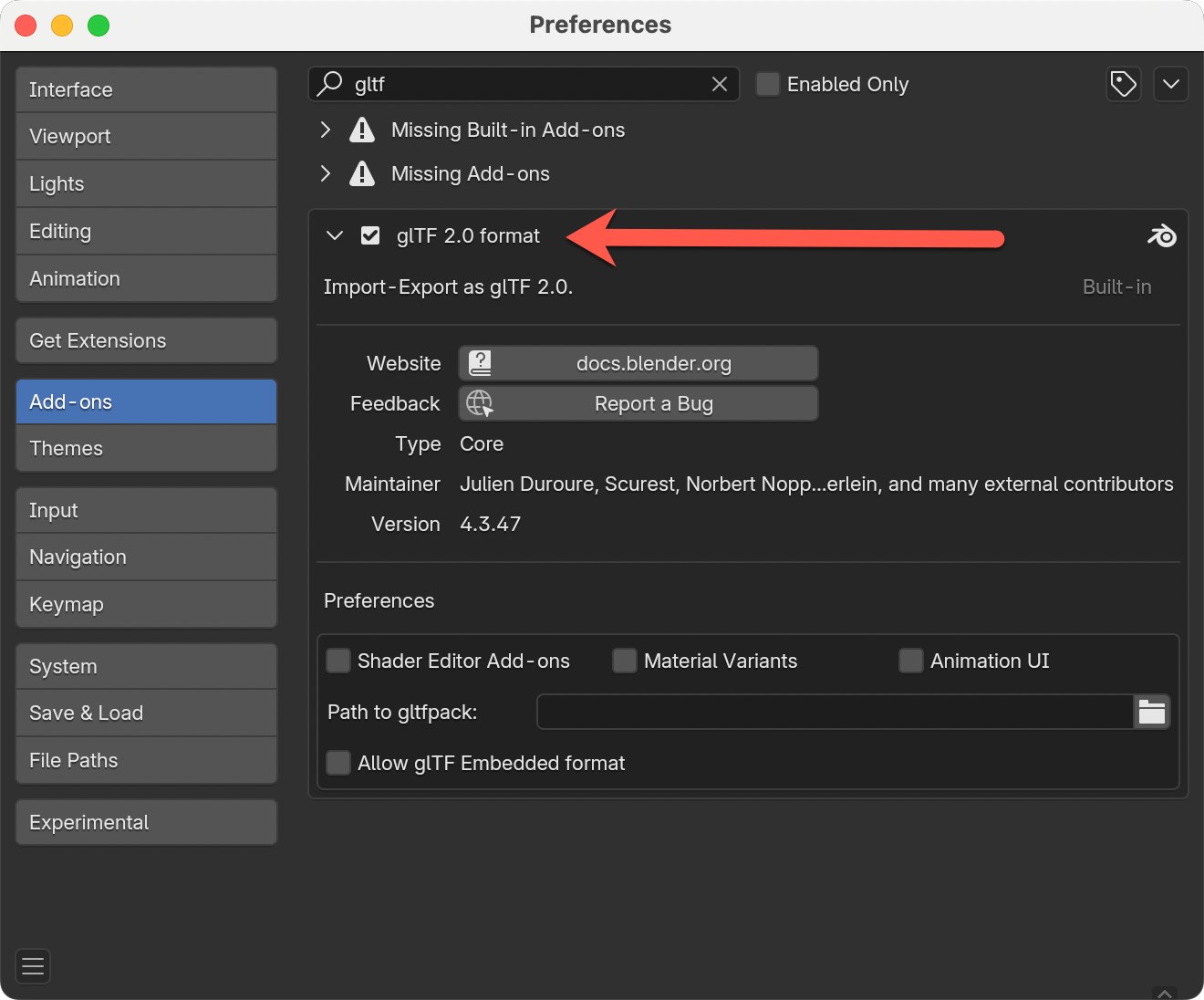
IMPORTANT : Make sure to enable the native Blender add-on called glTF 2.0 Format so you can export as GLB/glTF.
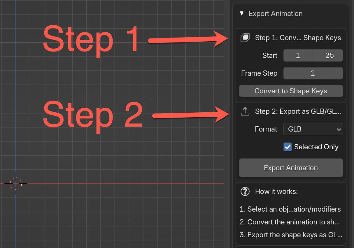
There are two steps involved.
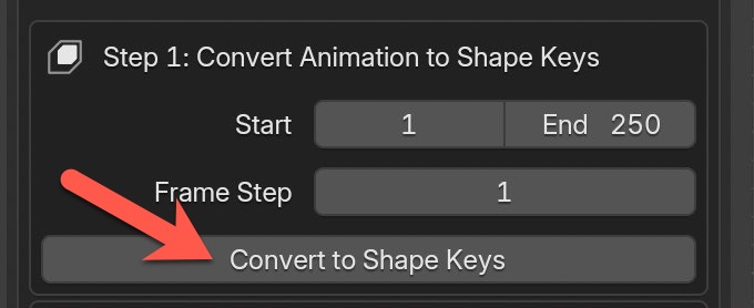
Step 1: Select the animated mesh object, adjust the start and end frame if needed, and then click on the button named Convert to Shape Keys. It can take a little time. This process will convert the entire animation into shape keys for each frame, which is important to do when exporting to GLB/GLTF.
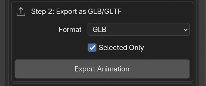
Step 2: Click on the Export Animation button shown. Another window will pop up that will prompt where you want to save the exported file. This step will take longer than the first step and the end result will typically be quite big.
That's it! After the process is complete you should the file in the specified directory. For testing purposes you can drag the newly exported file back into Blender and see if it works by playing the animation in Blender's timeline.
IMPORTANT: At this time, the feature cannot export each frame's material, but you should be able to re-assign each frame's material back after you import the GLB/GLTF file into another platform. I've successfully tested this importing back into Blender and re-assigning the materials that way...but I haven't tested on other platforms. It's a limitation with using the GLB/GLTF format. Only the first frame's material is exported. I hope to have an improved solution to pack each frame's materials into the exported file, but currently that isn't possible.
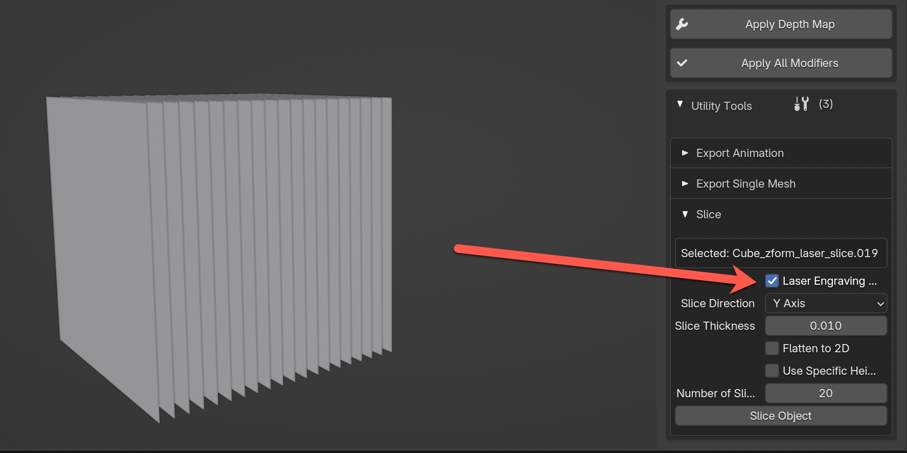
Slice Tool
The Slice Tool lets you cut your 3D model into multiple horizontal or vertical pieces that can be useful for things like laser engravings, cross-sections, or prepping models for layered exports.
Features
- Slice in any direction — X, Y, or Z axis
- Laser Mode — Create thin “engraving-like” slices with optional flattening
- Auto or Manual Slicing — Choose how many slices you want, or specify a single exact slice height
- Clean Results — The original object is hidden, and all slices are named automatically
How to Use
-
Select a Mesh Object
Make sure the object you want to slice is selected in the 3D Viewport. -
Open the Slice Tool Panel
Go to theUtility Toolssection and expand out Slice. -
Adjust Your Settings
- Toggle Laser Engraving Mode (optional)
- Choose the slicing axis (X, Y, or Z)
- Choose number of slices, or enable “specific height” for one precise cut
-
(Optional) Flatten slices if using Laser Mode
-
Click "Slice Object"
Sliced duplicates will be created based on your settings. The original will be hidden automatically.
Tips
- Use Laser Mode for thin slices that mimic engraving layers.
- Use Standard Mode to break up models into chunks or layers.
- Flattened slices are useful for generating heightmaps or laser-style lines.
- Choose X, Y, or Z slicing based on how your object is oriented.
Tips and Tricks
My Typical Workflow
I begin by expanding all the sections using the expand/collapse feature at the very top right and selecting my Input Type. Then I load the source—whether it's an image, video, or directory—and provide the corresponding depth map under Main Inputs, and change the Mesh View if necessary.
IMPORTANT: If you plan to use the Paint Mode feature to paint over depth maps, make sure to back up your original depth maps in an entirely separate directory because if you save the .blend files you will be prompted to save over and modify the depth map images.
As a starting point, I leave all features at their default values so that I can quickly generate the initial mesh. I typically use a Subdivision Levels value of 7 or 8 to keep performance smooth; I only increase it later if needed, and I drop back to 8 when making further mesh adjustments.
Once everything is set up, I scroll down to click the "Apply Depth Map" button. After the initial 3D mesh is generated, I collapse all sections to focus on fine-tuning individual features. At this stage, I adjust parameters like Depth Strength, tweak the mesh in the Mesh Properties (using the Deform Mesh feature), or use options in the Texture Properties (for example, turning it into a Shadow Box) — working on one section at a time to minimize on-screen clutter.
Only after everything is ready do I increase the Subdivision Levels above 8, though I often leave it as is. From my experience, if the depth map is in 8-bit, increasing the Depth Strength above 8 can negatively impact the mesh quality by introducing artifacts. I usually increase the Subdivision Levels above 8 only when using a 16-bit depth map.
The Importance of Depth Map Quality
The quality of depth maps is very important! I can't stress enough how much the end result of the 3D mesh is dependent on the original depth map created. That being said, there are also times when a lower quality depth map is fine, especially if you're just experimenting and learning how things work. It depends on your needs. But, typically I try to generate higher quality depth maps if I can.
For the most part, the standard size of depth map resolutions I believe is around 500. For example, using the web platform Hugging Face to generate depth maps will most likely produce a depth map in this resolution size. Whereas if you use a local tool like ComfyUI or other local tools like my other add-on Depth Map Batch, you'll have more control on resolution size to go higher to sizes like 1200 or even 1600 if your computer can handle it. But, they also take more time to generate.
In an ideal scenario you want to find a tool that can give you control on specifying the resolution size. And if you have the option to also generate 16-bit depth maps, that will help a lot with banding issues that can happen in the mesh when using 8-bit depth maps. But, again....it isn't necessary to have these options if you don't have them available. There's plenty you can do to experiment and get a sense of this workflow.
How can I remove the unwanted fold at the top of the image?
Do you want remove this unwanted folding at the top that can happen sometimes when generating the mesh?
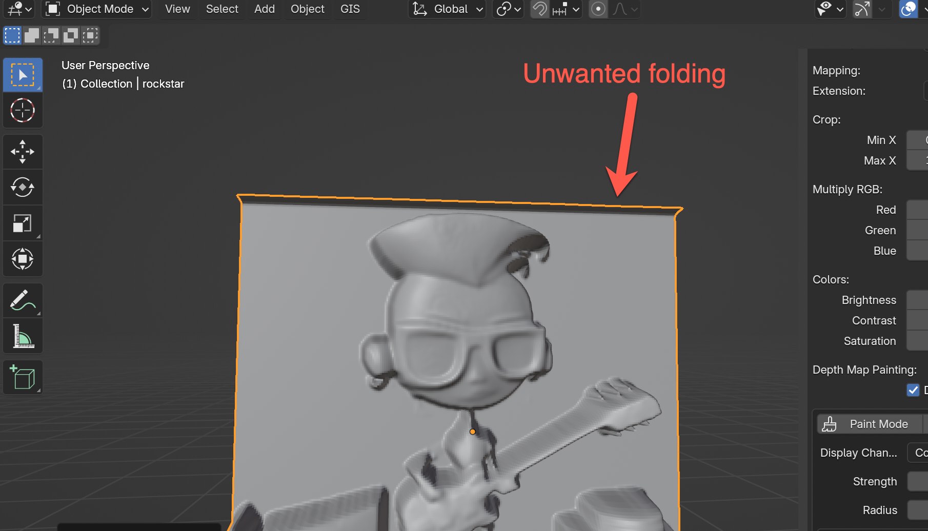
The fastest way to do that is go into the Texture Properties section and change the Mapping Extension option to Extend.
Exporting Mesh
For those using zForm to export meshes with materials, please ensure you disable the "Use Transparency" option in the Material Properties section before export. This step simplifies the material and helps preserve the original image colors.
Also make sure to do simple cleanup techniques of the mesh like removing duplicate vertices.
Saving and Working with Existings Project Files
I discovered that the “Relative Paths” setting in Blender’s Preferences was causing problems when reusing saved projects. To fix this, please uncheck "Relative Paths" in the Save and Load window in Preferences.
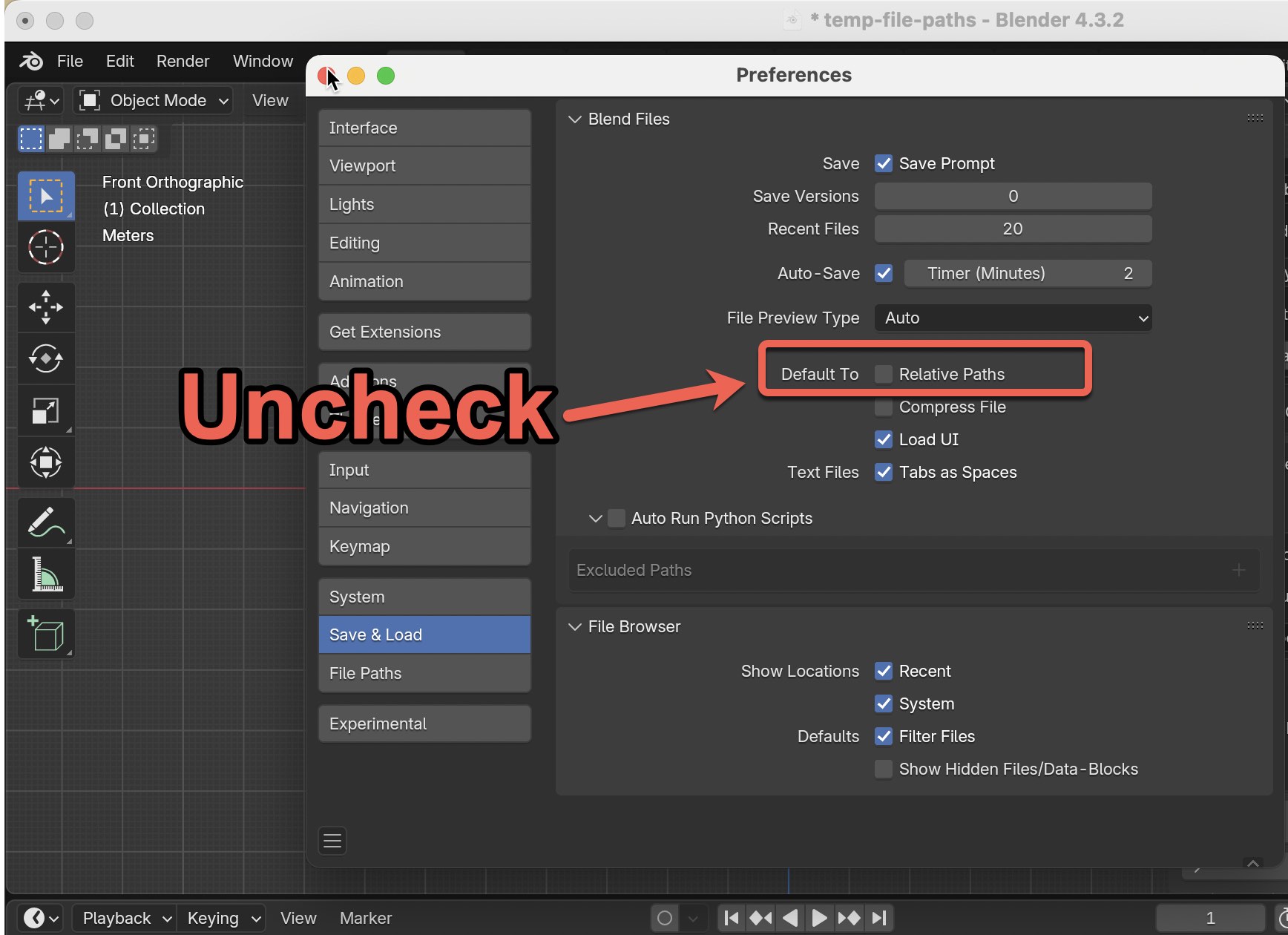
You can follow these steps:
- Open Blender and go to Edit → Preferences.
- In the Preferences window, navigate to the Save And Load section.
- Uncheck the "Relative Paths" option in the Default To section.
- In the bottom left of the Preferences window, click on the hamburger icon to save your preferences.
- This change will be saved for all future project files. If you ever need to revert to the previous behavior, simply re-check the "Relative Paths" option.
Additional Note for zForm Users: When reopening an older project in zForm, please note that the Mesh View option defaults to top view. You may need to adjust this setting manually.
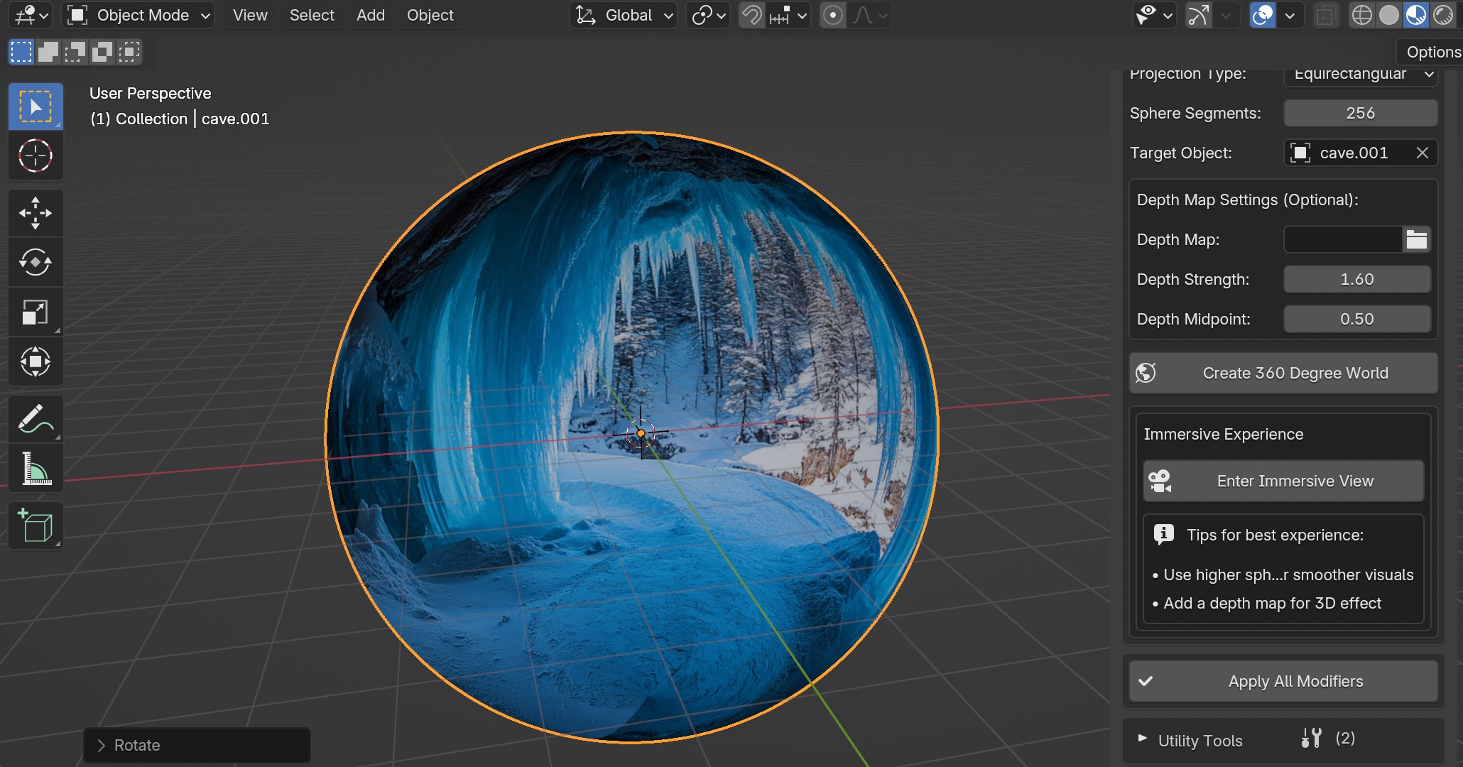
How to create 360 degree world using Explore 360
Here are the steps involved to create a 360 degree world using the input type for Expore 360. Accepted image formats include png, jpg, jpeg, exr, tiff, tif, and hdr. The ideal type of image to use is equirectangular, which will help produce seamless textures, but other images are fine to use too (2:1 aspect ratios are best).
You can create free equirectangular images using Rosebud.AI here.
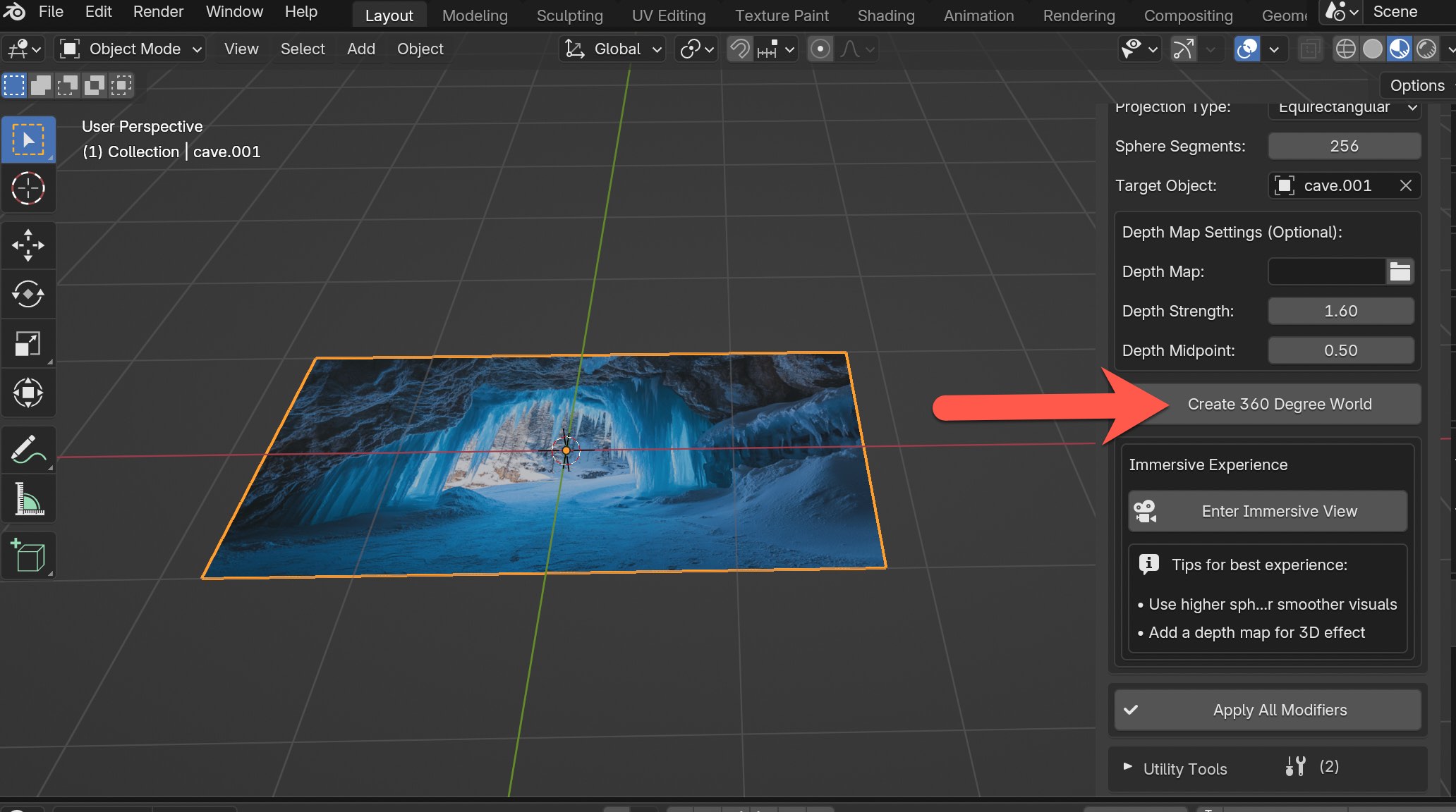
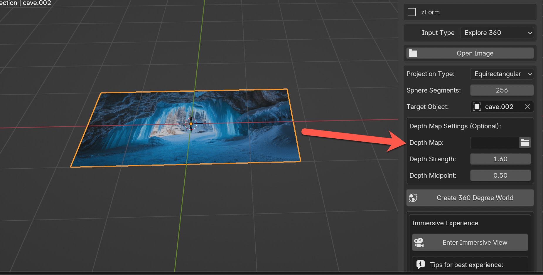
Step 1: In the Input Type dropdown menu at the very top choose Explore 360 option.
Step 2: Click on the Open Image button to import your image and you should see the image imported in as a flat plane object.
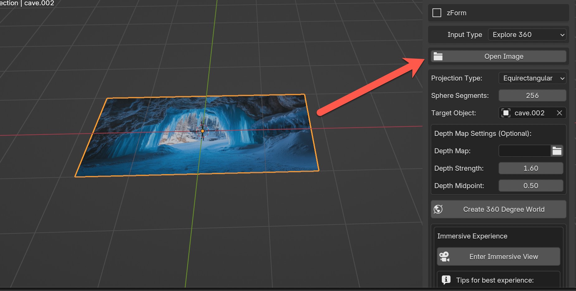
Step 3 (Optional): This step is option. If you'd like to use a corresponding depth map that matches the original image you can do so here. For this example I'm going to leave empty and adjust any necessary inputs as needed.
Step 4: Click on the Create 360 Degree World button to create an immersive world for your image.
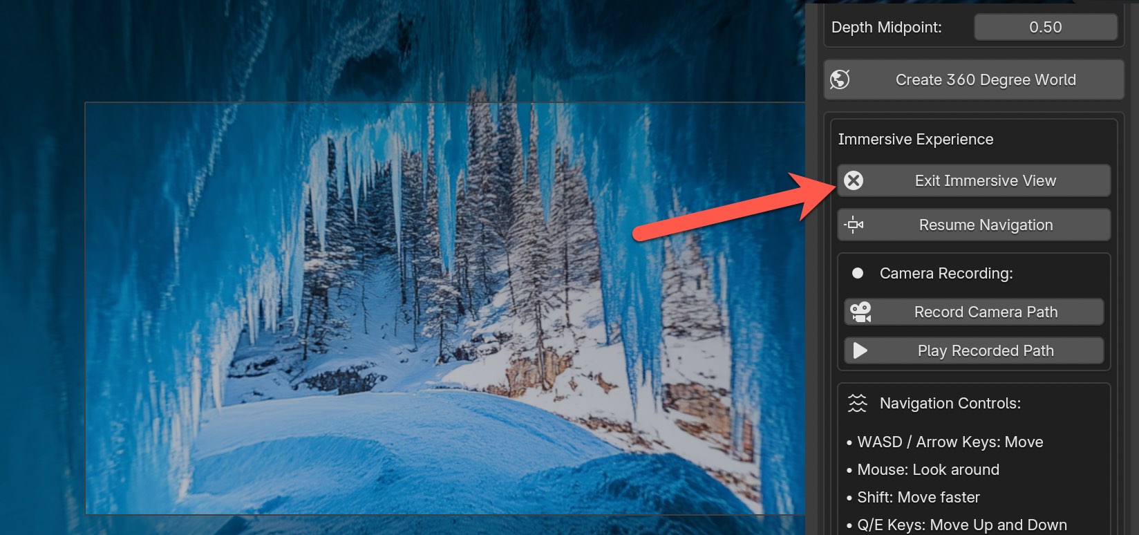
Step 5: Click on the Enter Immersive View button to explore inside of the 360 degree world.
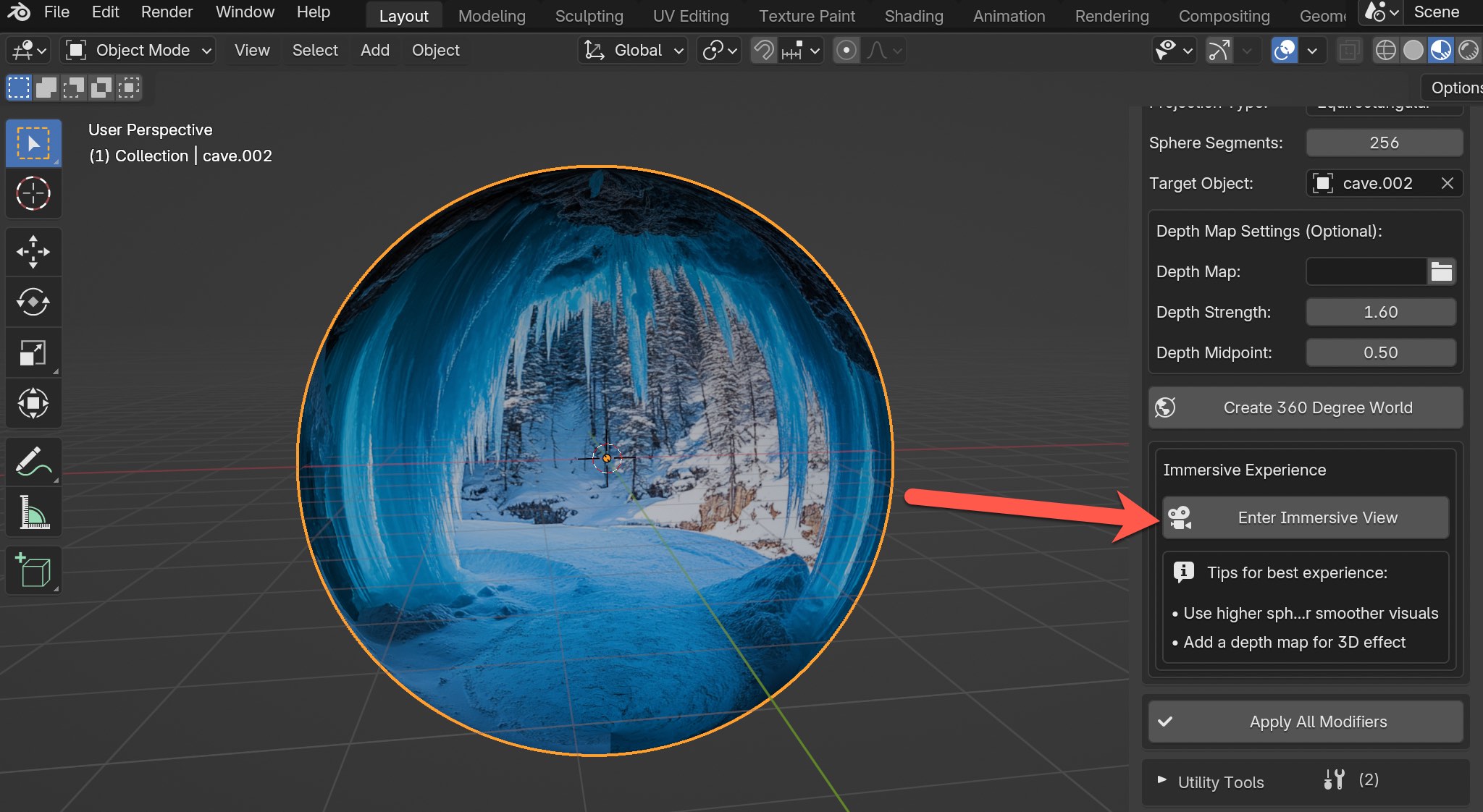
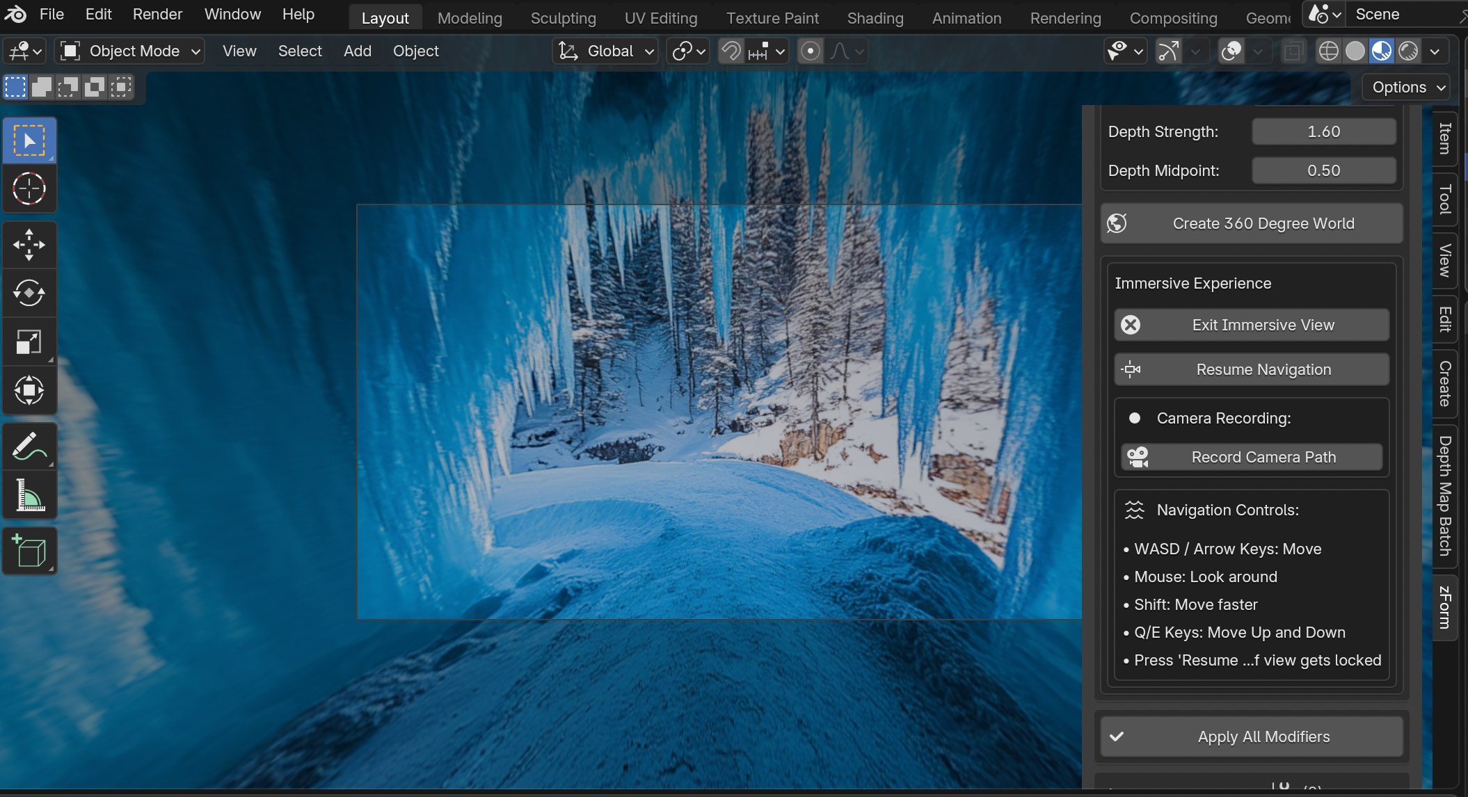
You should see something like this.
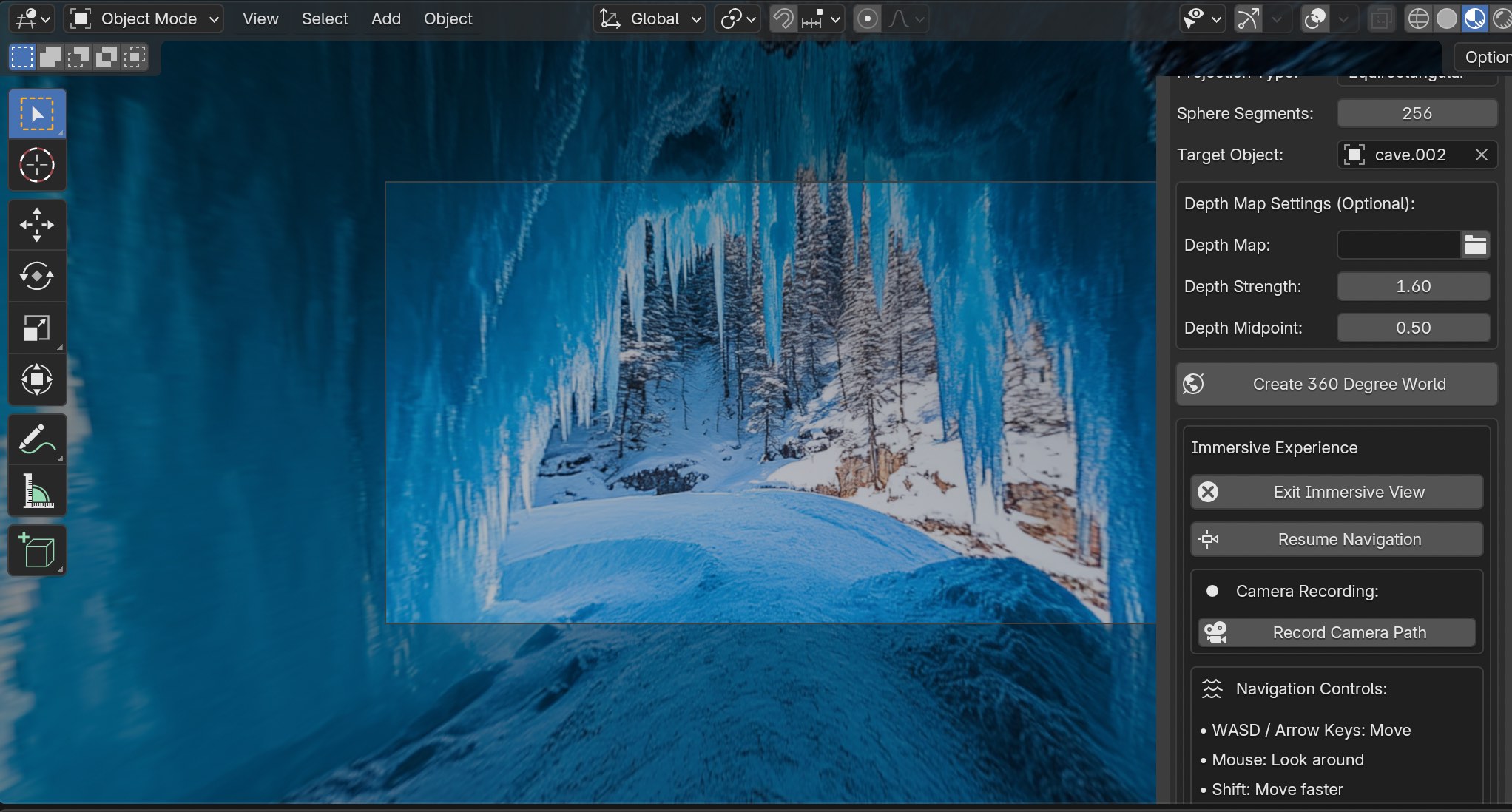
Now look on the right side for some tips on how to use the keyboard and mouse to navigate around the world. If you simply want to turn around 360 degrees use the mouse or touchpad. For moving up and down use the keys Q and E. And then to move forward and backward use W and S, and for left and right use A and D.
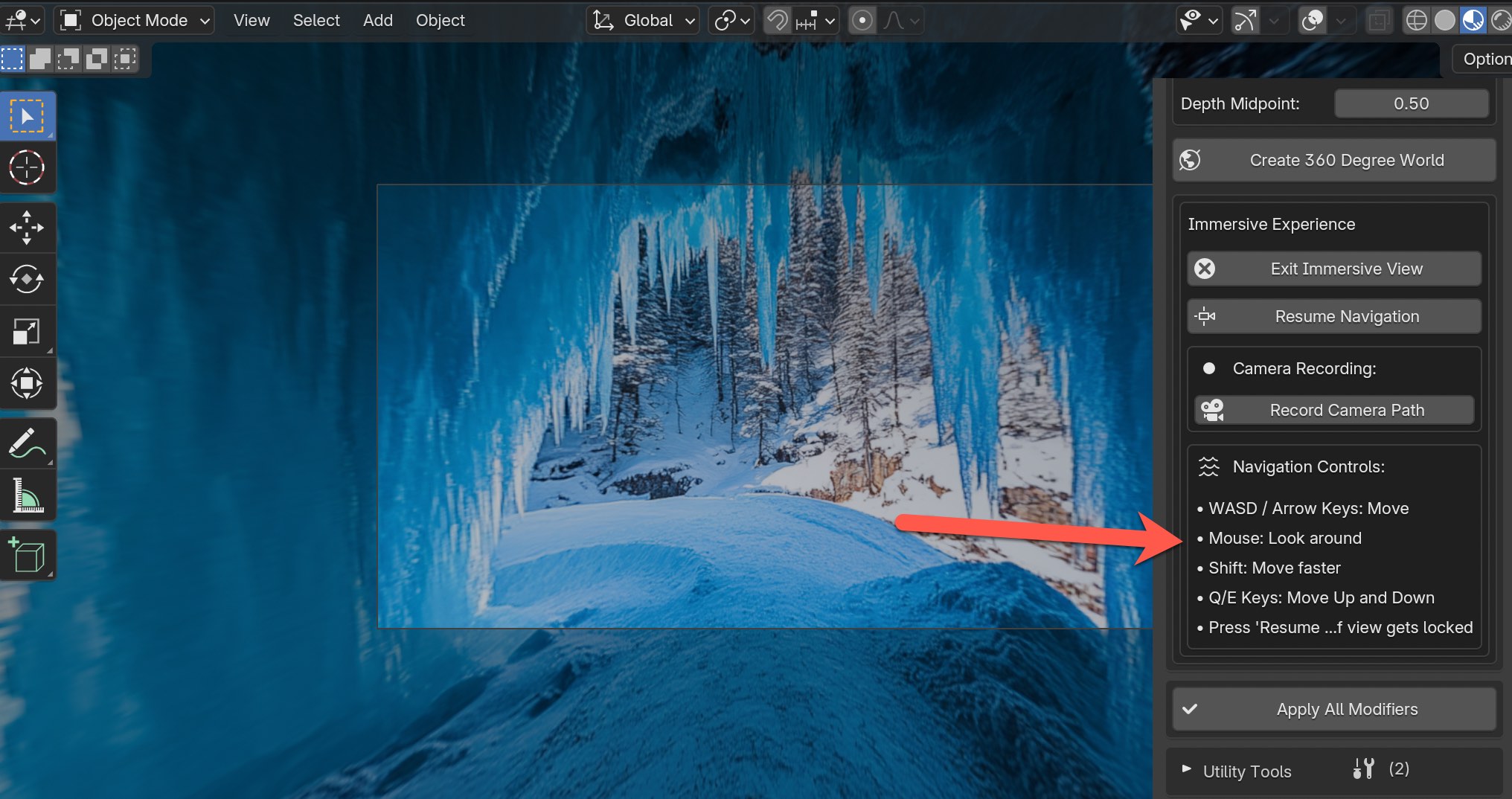
At any time you can click with your mouse or touchpad to stay in place. And if you want to start moving around again click on the Resume Navigation button.
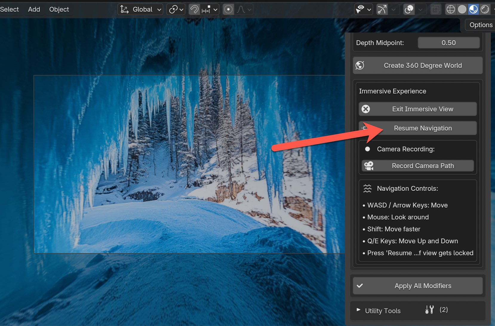
Another fun feature when you're inside of the immersive experience for Explore 360 is the ability to record the camera path, which in turn will allow you later on to render frames that can be turned into a video.
Just click on the Record Camera Path button to start recording.
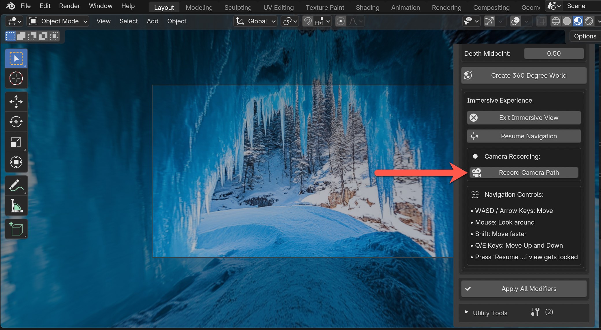
At any time you can click on Stop Recording to stop recording.

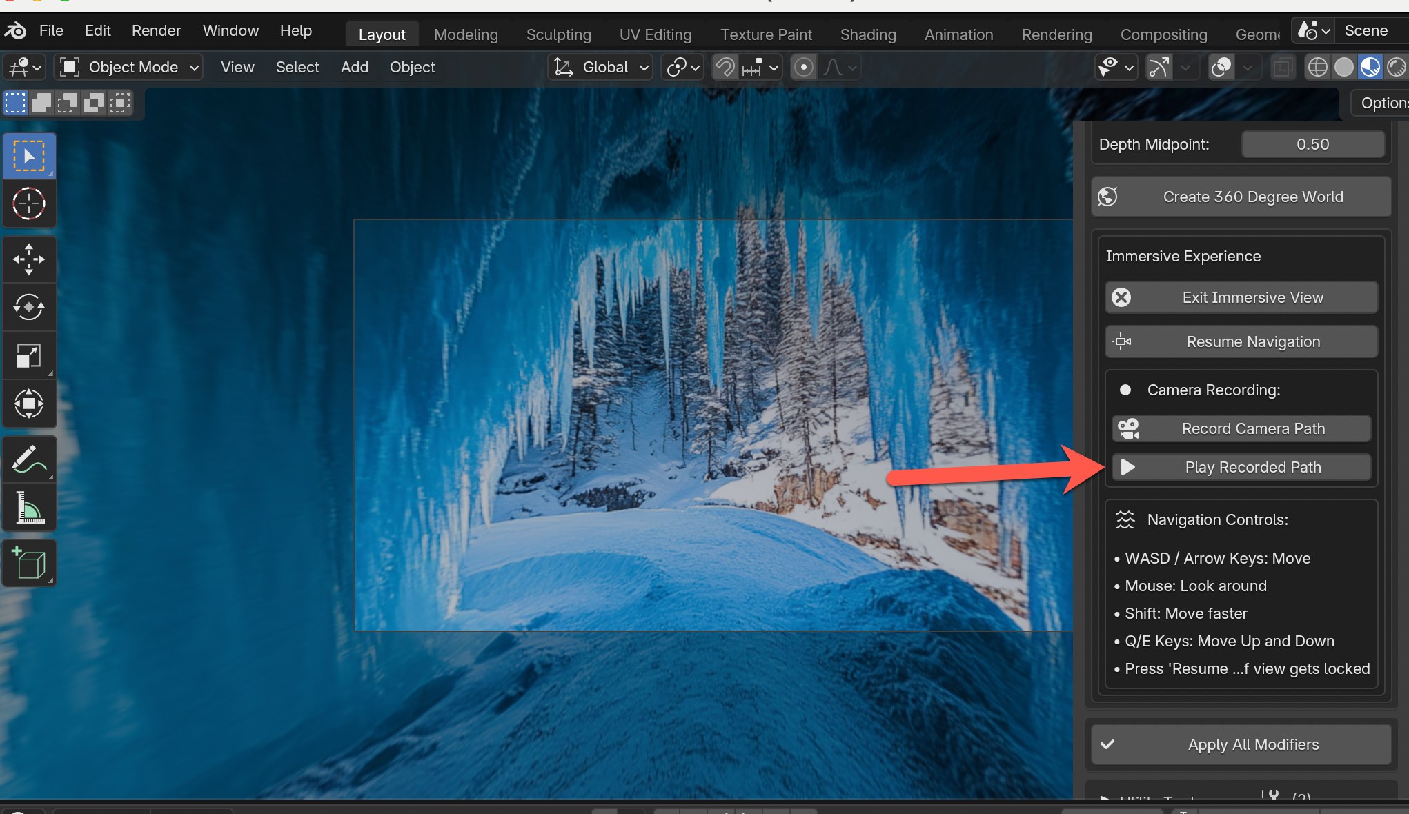
Afterwards you have the option to play the recorded path by pressing the Play Recorded Path button or alternatively at any time you can press space on your keyboard to play the animation.
Last, but not least once you're ready to exit the immersive experience click on the Exit Immersive View button.
And that should take you completely out of the 360 degree world like this.
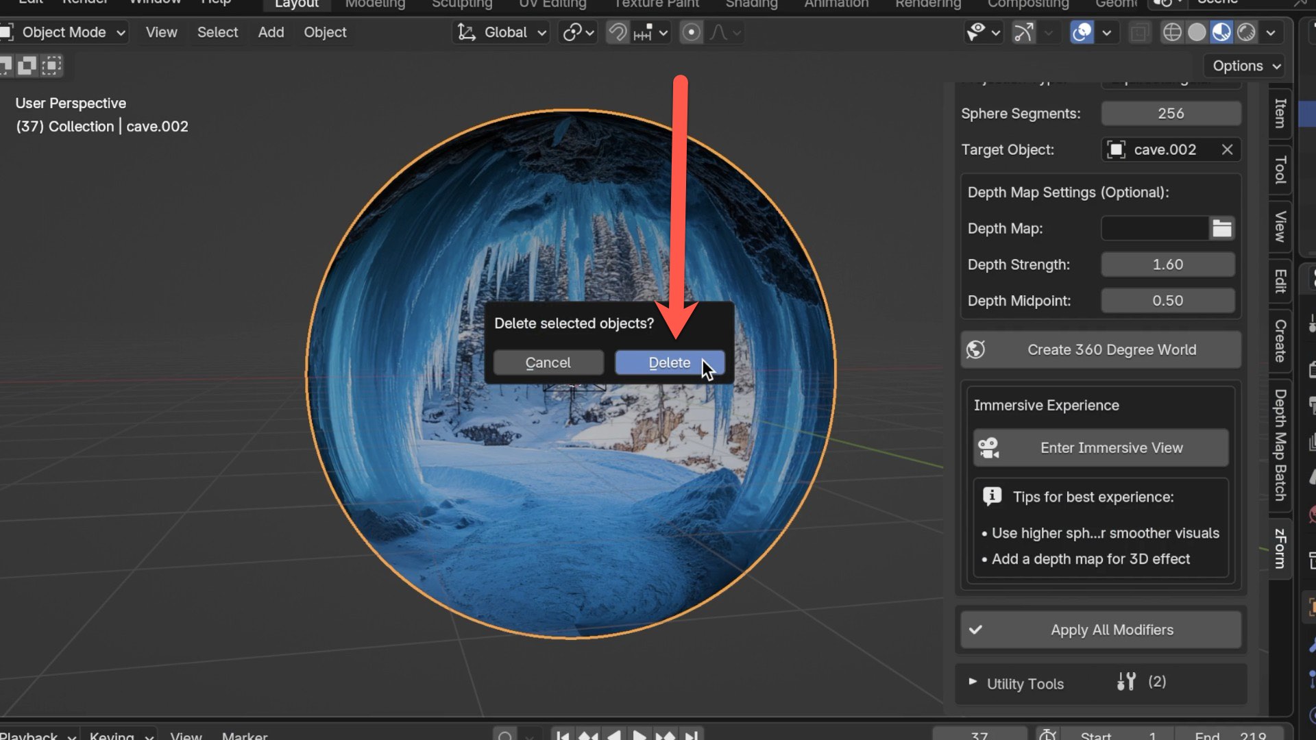
If you want to try creating a new 360 degree world select the existing one and type in the letter "x" on your keyboard and click on Delete and start over using the same steps again.
Current Issues
- In Paint Mode for the Video input type, the Reset feature in Texture Properties isn't functioning correctly for specific frames. It will handle painting just fine for each frame, but resetting a the texture specific frame th
Newest Updates
Check out all the release and code updates here